
Metal components with inert vapor phase coating on internal surfaces

a technology of metal components and internal surfaces, applied in the field of coating metal components, can solve the problems of difficult formation of peek into many required shapes and sizes of lc components, inability to readily obtain, and not as strong as metal mechanically

Inactive Publication Date: 2015-01-22
AGILENT TECH INC
View PDF13 Cites 21 Cited by
  • Summary
  • Abstract
  • Description
  • Claims
  • Application Information

AI Technical Summary

Benefits of technology

The invention is a method for coating metal components to prevent corrosion and interference in LC analyzes. It can also be used to coat long metal tubes and small channels with a continuous coating that adheres to metal surfaces. The method makes the metal flow path compatible with bioanalytical separations by rendering it inert. The coated components can be used for LC separations without affecting the analysis results.

Problems solved by technology

Many samples analyzed by LC have no interaction with metal, but some samples, particularly those in bio-analytical applications, are sensitive to leached metal ions and / or are prone to interaction with metal surfaces giving rise to interference with the analytical process or impurities in the isolated components.
In addition to being expensive, PEEK is difficult to form into many required shapes and sizes of LC components, and not readily available in all forms that are desired.
Additionally, PEEK is not as strong as metal mechanically and is therefore unable to withstand the pressures (typically above about 400 bar) that are used for ultra-high pressure LC (UHPLC).
Another approach is to use a glass tube inserted into a jacket made of metal or plastic, which has limited applications to LC components.
Conventional approaches and existing alternative designs have exhibited the disadvantages of not adhering well to the metal surfaces being protected, not being able to coat uniformly down long lengths of small tubing, and not being able to coat small channels (e.g., 5-10 μm diameter).

Method used


Image

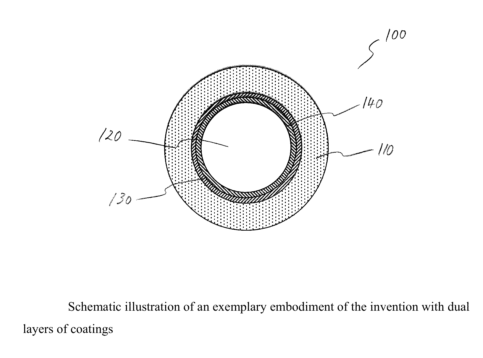
  • Metal components with inert vapor phase coating on internal surfaces
  • Metal components with inert vapor phase coating on internal surfaces
  • Metal components with inert vapor phase coating on internal surfaces

Examples


example 1

Amorphous Si Coating

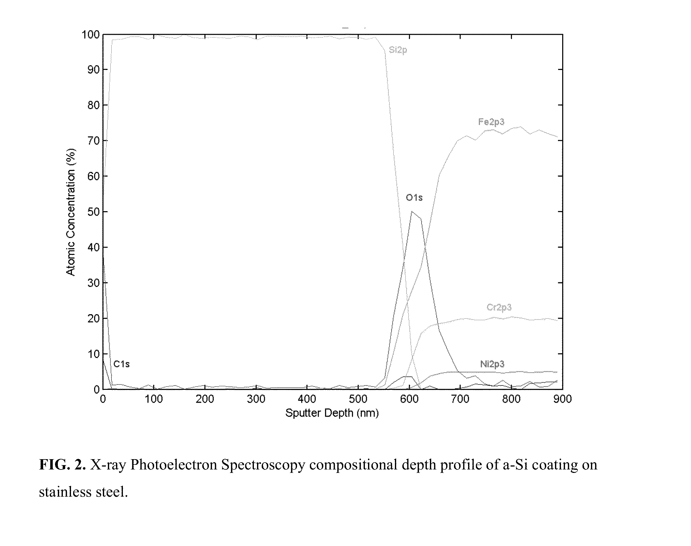
[0040]The first coating, an amorphous Si coating, was deposited on stainless steel coupons, frits and HPLC columns, and on titanium coupons. Deposition was done by thermal chemical vapor deposition in a closed reactor using SiH4 gas as a molecular precursor. Temperature for deposition was between 350° C. and 450° C. and partial pressure of SiH4 in the reactor was between 50-1000 mbar in dry nitrogen gas. Two depositions were done in succession to achieve a coating thickness of 550 nm on coupons and 100 nm in the interior of the HPLC column. Coating thickness on the coupons was measured using spectral reflectance and verified by X-ray Photoelectron Spectroscopy. Coating thickness on the column interior was estimated from the relative intensities of the

[0041]Fe K series and Si K series lines from Energy Dispersive X-ray Spectroscopy, compared to relative intensities on flat surfaces with known a-Si thickness. Thickness of the coating on titanium coupons, deposited ...

example 2

Polymeric Siloxane Coating

[0044]The second coating, a polymeric siloxane coating, was deposited using chemical vapor deposition at a temperature between 350° C. and 450° C. Coating thicknesses of 100 nm to 300 nm were achieved on stainless steel coupons, stainless steel fits, and on the interior surface of HPLC columns. All parts demonstrated greater than 10× reduction in metal ion concentration released into solution when soaked in 0.1% formic acid. In addition, a siloxane coated HPLC column was packed with silica beads held in place by two siloxane-coated frits. This column showed superior performance to a stainless steel column with stainless steel frits in a liquid chromatography separation of Cytochrome C, an enzyme known to be sensitive to metal ions.

example 3

Bilayer Coating (Si / Siloxane)

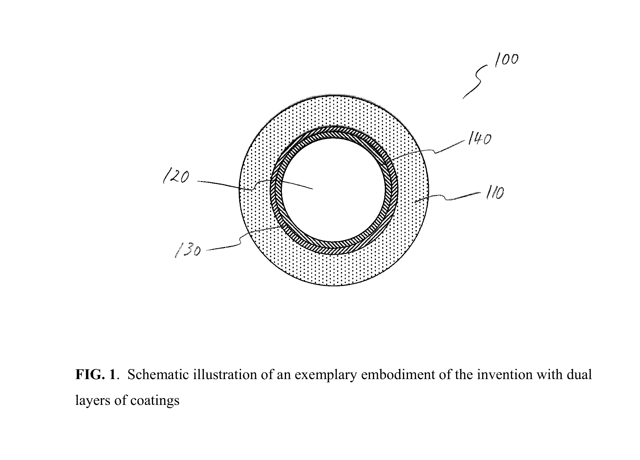
[0045]The third coating was a bilayer consisting of 200 nm of a-Si directly on the stainless steel, covered by 150 nm of siloxane coating on the a-Si. This coating was deposited by the above described chemical vapor deposition processes on stainless steel coupons. These coupons demonstrated 10X reduction in metal ion concentration after soaking in 0.1% formic acid. A similar bilayer was also deposited on the interior surface of an HPLC column and demonstrated a superior liquid chromatography separation of Cytochrome C compared to a stainless steel column.

[0046]FIG. 3 shows comparison of ions leached into solution from 2×3 cm stainless steel coupons coated with a-Si, siloxane, and Si / Siloxane bilayer compared to ions leached from uncoated stainless steel. Coupons were soaked in 0.1% formic acid at 50C for four days. Metal ion concentration in solution measured by Inductively Coupled Plasma-Mass Spectrometry.


PUM

PropertyMeasurementUnit
Lengthaaaaaaaaaa
Lengthaaaaaaaaaa
Lengthaaaaaaaaaa

Abstract

The invention provides metal liquid chromatography components with uniformly coated internal surfaces and methods for achieving the same. The invention addresses the problem of corrosion or interference of metal components in the flow path for LC analyses in which the sample interacts with metal ions or surfaces. The invention also alleviates the difficulties in coating very long metal tubes and very small metal channels with an inert, continuous coating that adheres well to metal surfaces. The metal flow path is rendered inert by the coating, and thus compatible with bioanalytical separations, for example, by using a vapor phase deposition process to coat the inner surfaces with a coating that continuously covers all metal surfaces in the flow path.

Description

FIELD OF THE INVENTION [0001]The invention generally relates to coated metal components and related methods. More particularly, the invention relates to metal liquid chromatography components with uniformly coated internal surfaces and methods for achieving the same.BACKGROUND OF THE INVENTION[0002]Liquid chromatography (LC) is a chromatographic technique used to separate a mixture of compounds with the purpose of identifying, quantifying or purifying the individual components of the mixture. This separation occurs based on the interactions of the sample with the mobile and stationary phases. There are many stationary / mobile phase combinations that can be employed when separating a mixture. Liquid-solid column chromatography, the most popular chromatography technique, features a liquid mobile phase that slowly filters down through the solid stationary phase, bringing the separated components with it.[0003]LC uses many metal components for transport of liquid. Examples include pump c...

Claims


Application Information

Patent Timeline
IPC IPC(8): C23C16/40B01D15/22C23C16/24C23C16/44
CPCC23C16/24C23C16/44B01D15/22C23C16/403C23C16/405C23C16/45555C23C16/045C23C16/30Y10T428/13G01N2030/567C23C16/325C23C16/401
Inventor CARR, ELIZABETHSEAWARD, KAREN LKILLEEN, KEVIN P
Owner AGILENT TECH INC
Learn More