Lifetime ion source

a life-time ion source and ion source technology, applied in the field of ion implantation, can solve the problems of boron ion (bsup>+/sup>) implantation, high-throughput, and limited life of ihc ion sources, and achieve the effect of improving ion source performan

Inactive Publication Date: 2015-02-05
VARIAN SEMICON EQUIP ASSOC INC
View PDF10 Cites 19 Cited by
  • Summary
  • Abstract
  • Description
  • Claims
  • Application Information

AI Technical Summary

Benefits of technology

[0004]Embodiments are directed to methods and apparatus for improved ion source performance. In one embodiment an ion source includes an ion source chamber, a gas source to provide a fluorine-containing gas species to the ion source chamber, a cathode disposed in the ion source chamber and configured to emit electrons to generate a plasma within the ion source chamber, the ion source chamber and cathode comprising a refractory metal; and a phosphide insert disposed within the ion source chamber and presenting an exposed surface area that is configured to generate gas phase phosphorous species when the plasma is present in the ion source chamber, wherein the phosphide component is one of boron phosphide, tungsten phosphide, indium phosphide, aluminum phosphide, nickel phosphide, and calcium phosphide.

Problems solved by technology

In particular, the lifetime of an IHC ion source is typically limited by the lifetime of the cathode and repeller components of the ion source.
As a result, an uncontrollable growth of tungsten may occur on some electrode surfaces, which can result in glitching during operation of the ion source.
Moreover, as irregular growth of redeposited metallic material proceeds, such growth may result in electrical shorting between electrodes and chamber walls of the ion source, making ion source operation impossible.
In particular, high-throughput, boron ion (B+) implantation that employs processes gasses that contain fluorine may experience increased glitching over time during operation.
This may increase down time of an ion implantation apparatus and increase production and equipment costs.

Method used


Image

  • Lifetime ion source
  • Lifetime ion source
  • Lifetime ion source

Examples


Embodiment Construction

[0012]The present disclosure will now be described more fully hereinafter with reference to the accompanying drawings, in which some embodiments are shown. The subject of this disclosure, however, may be embodied in many different forms and should not be construed as limited to the embodiments set forth herein. Rather, these embodiments are provided so that this disclosure will be thorough and complete, and will fully convey the scope of the subject of this disclosure to those skilled in the art. In the drawings, like numbers refer to like elements throughout.

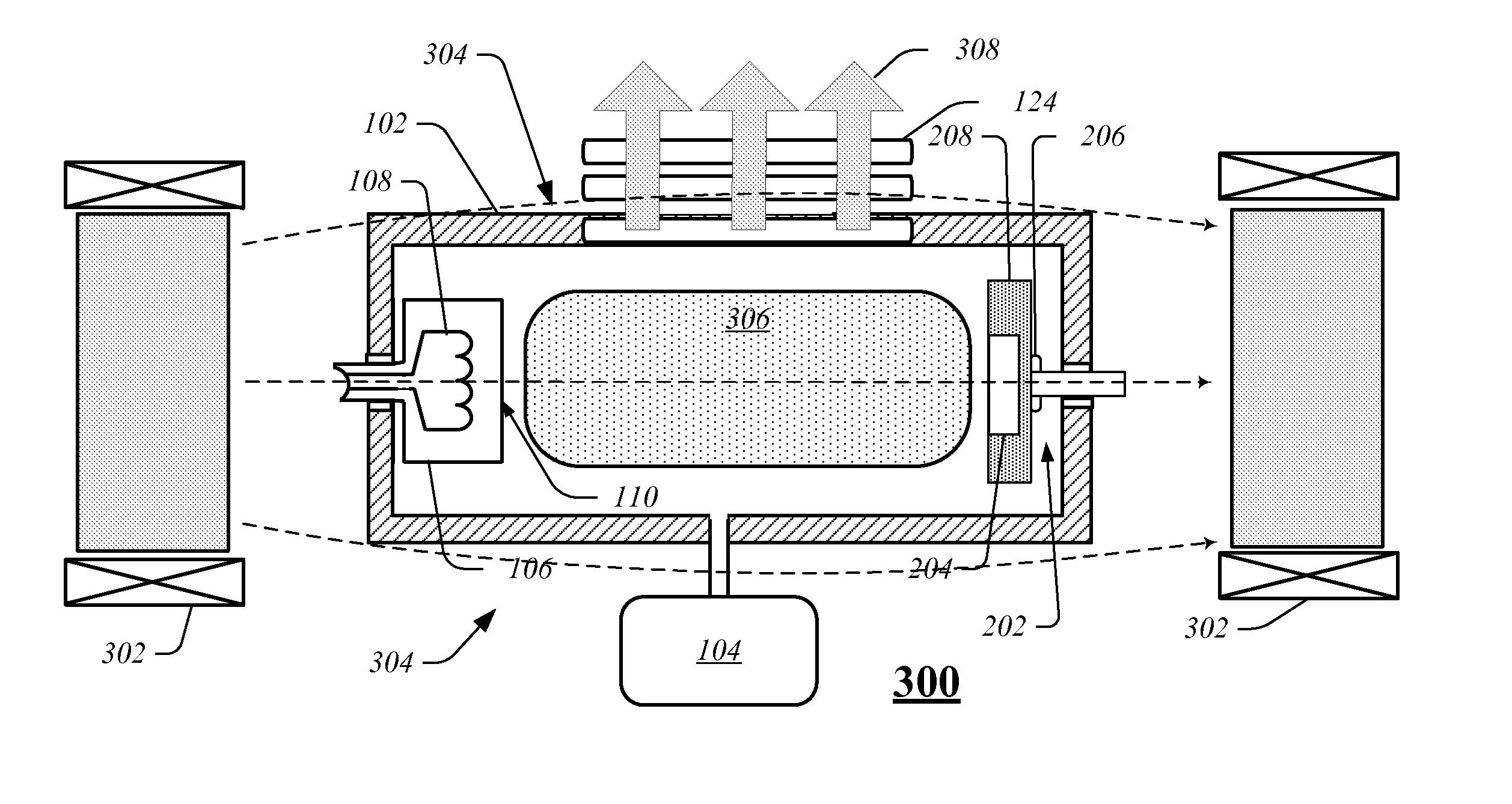
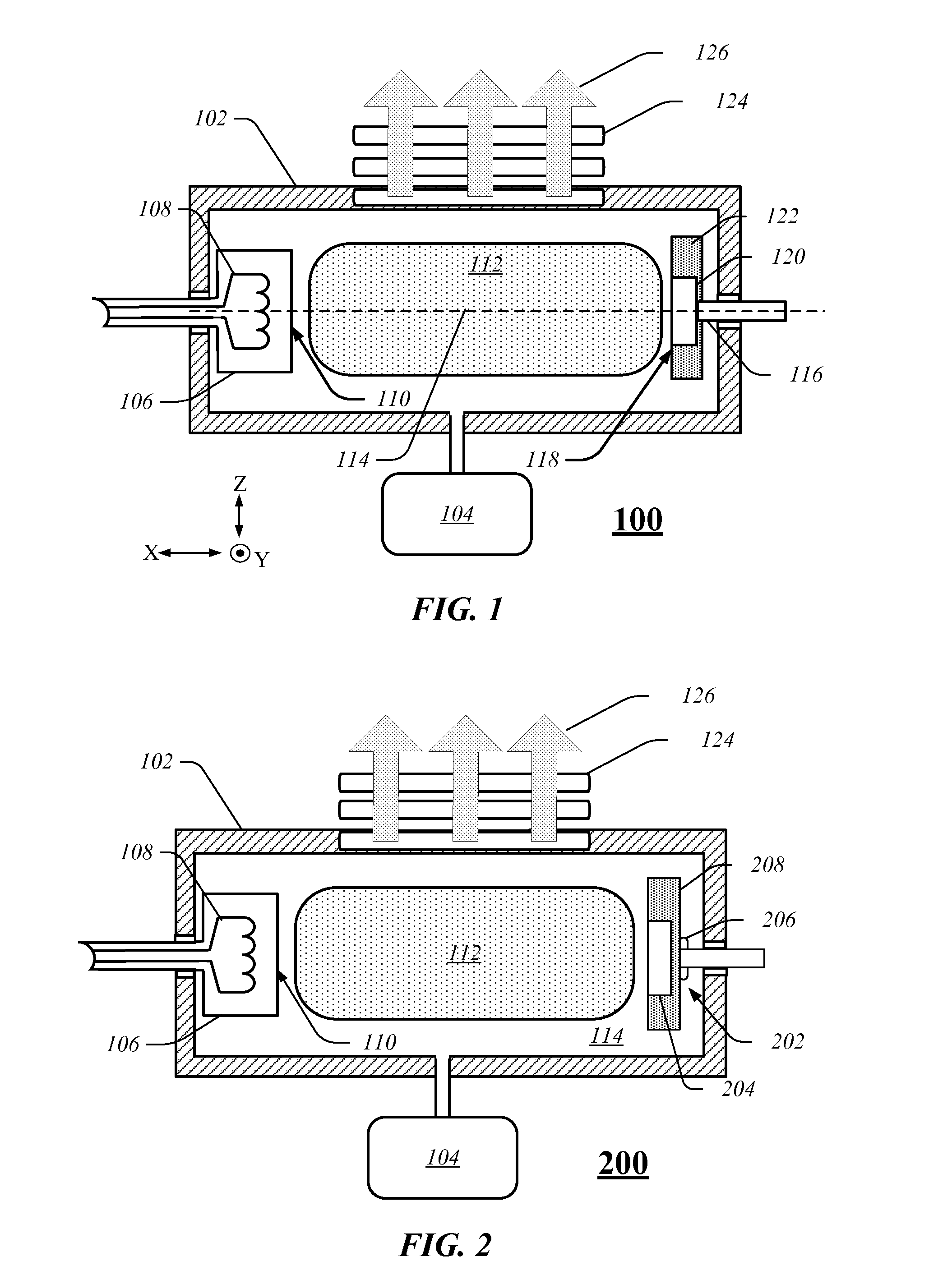
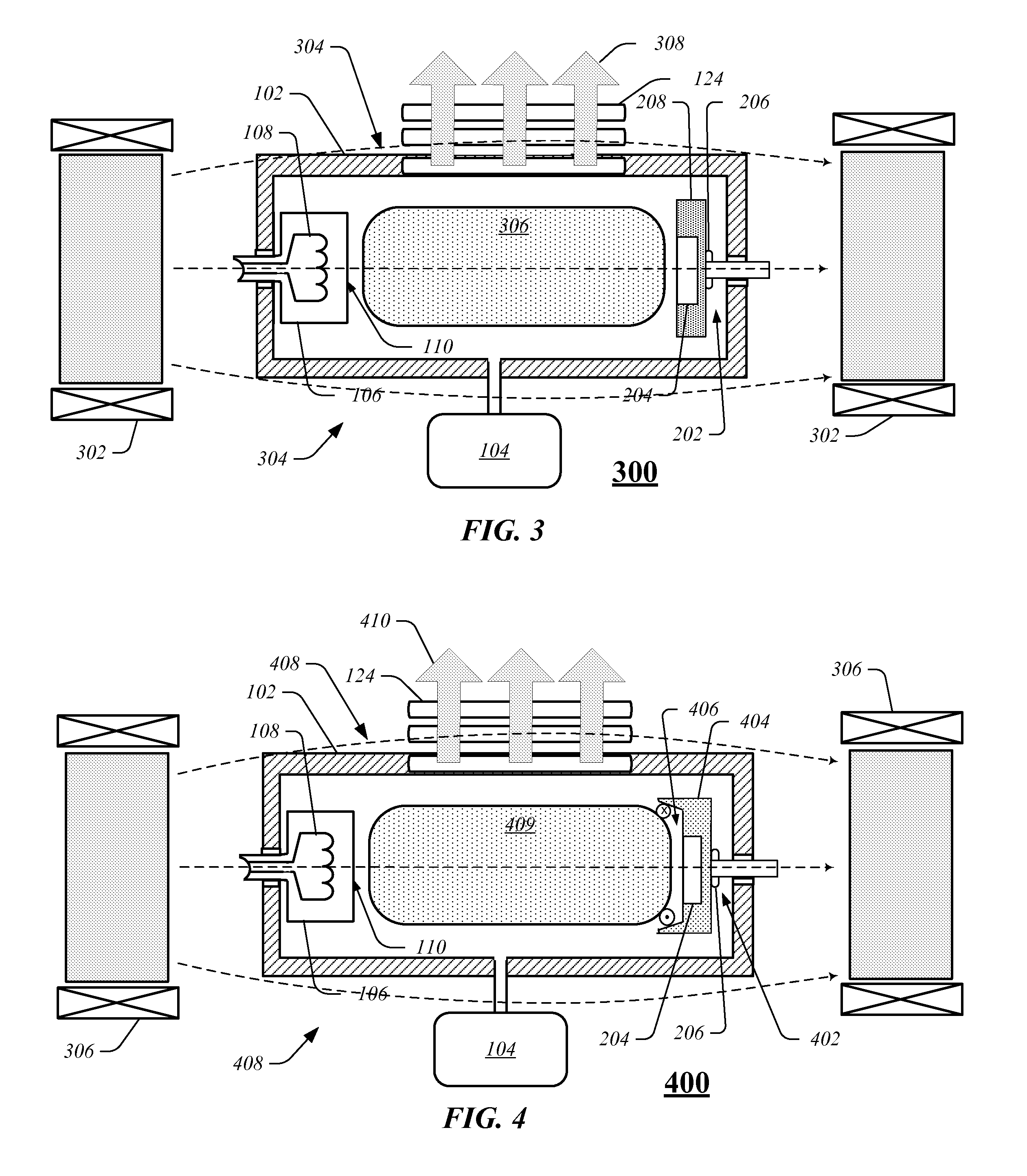
[0013]In various exemplary embodiments, ion sources are configured to improve performance and / or extend operating life of an ion source. Ion sources arranged according to the present embodiments include those ion sources that are constructed from refractory metal materials and designed to operate at elevated temperatures. Included among such ion sources are indirectly heated cathode (IHC) style ion sources in which a cathode ma...


PUM


Abstract

An ion source includes an ion source chamber, a gas source to provide a fluorine-containing gas species to the ion source chamber and a cathode disposed in the ion source chamber configured to emit electrons to generate a plasma within the ion source chamber. The ion source chamber and cathode are comprised of a refractory metal. A phosphide insert is disposed within the ion source chamber and presents an exposed surface area that is configured to generate gas phase phosphorous species when the plasma is present in the ion source chamber, wherein the phosphide component is one of boron phosphide, tungsten phosphide, aluminum phosphide, nickel phosphide, calcium phosphide and indium phosphide.

Description

FIELD[0001]Embodiments relate to the field of ion implantation. More particularly, the present embodiments relate to apparatus and method for producing improved ion sources.BACKGROUND[0002]Ion sources such as indirectly heated cathode (IHC) ion sources are used to generate a variety of ion species including dopant ions that are used for implantation into semiconductor substrates to control their electronic properties. Many precursors for dopant ions contain halogen species such as fluorine (BF3, B2F4, GeF4, PF3, SiF4, AsF5, etc), which can create a corrosive environment within an ion source. In particular, the lifetime of an IHC ion source is typically limited by the lifetime of the cathode and repeller components of the ion source. During operation, portions of the ion source that are exposed to halogens such as fluorine-containing gas species may be subject to etching. For example, ion source components may be constructed at least partially from tungsten that is exposed to fluorin...

Claims


Application Information

Patent Timeline
Patent Type & Authority Applications(United States)
IPC IPC(8): H01J27/02H01J27/20
CPCH01J27/205H01J27/022
Inventor KOO, BON-WOONGLEVAY, WILLIAM T.WHITE, RICHARD M.COBB, ERIC R.
Owner VARIAN SEMICON EQUIP ASSOC INC
Why Eureka
Try Eureka