Check patentability & draft patents in minutes with Patsnap Eureka AI!

Charged particle beam writing method and charged particle beam writing apparatus

Active Publication Date: 2015-02-12
NUFLARE TECH INC
View PDF11 Cites 5 Cited by
  • Summary
  • Abstract
  • Description
  • Claims
  • Application Information

AI Technical Summary

Benefits of technology

The present invention provides a charged particle beam writing method and apparatus that can efficiently divide a writing region of a target object into a plurality of stripe regions and calculate the total area of a pattern assigned to each stripe region and the number of shots of a charged particle beam needed for writing the pattern. The method and apparatus can also determine whether a difference between the total area and the number of shots exceeds a threshold value and re-divide the stripe region accordingly to minimize the difference. The technical effects of the invention include improved efficiency and accuracy in charged particle beam writing.

Problems solved by technology

In electron beam writing, there is a problem in that if a pattern density greatly varies during writing, the position accuracy of a pattern is degraded at the place of varying.
However, if the stripe width is set to be narrow, there occurs a problem in that the throughput is reduced because the number of stripes set in the target object is greatly increased.
Therefore, this method is not desirable.
However, with respect to the place where the pattern density sharply changes, drift correction has difficulty in following the beam position variation.
Therefore, required position accuracy has not been obtained.
Although it is necessary to set the time interval to measure a beam drift amount to be very short for dealing with even the case of the sharp variation of a pattern density, the writing operation needs to be stopped when measuring the beam drift amount, which poses a problem of throughput decrease.
Therefore, this method is not desirable, either.

Method used


Image

  • Charged particle beam writing method and charged particle
beam writing apparatus
  • Charged particle beam writing method and charged particle
beam writing apparatus
  • Charged particle beam writing method and charged particle
beam writing apparatus

Examples


first embodiment

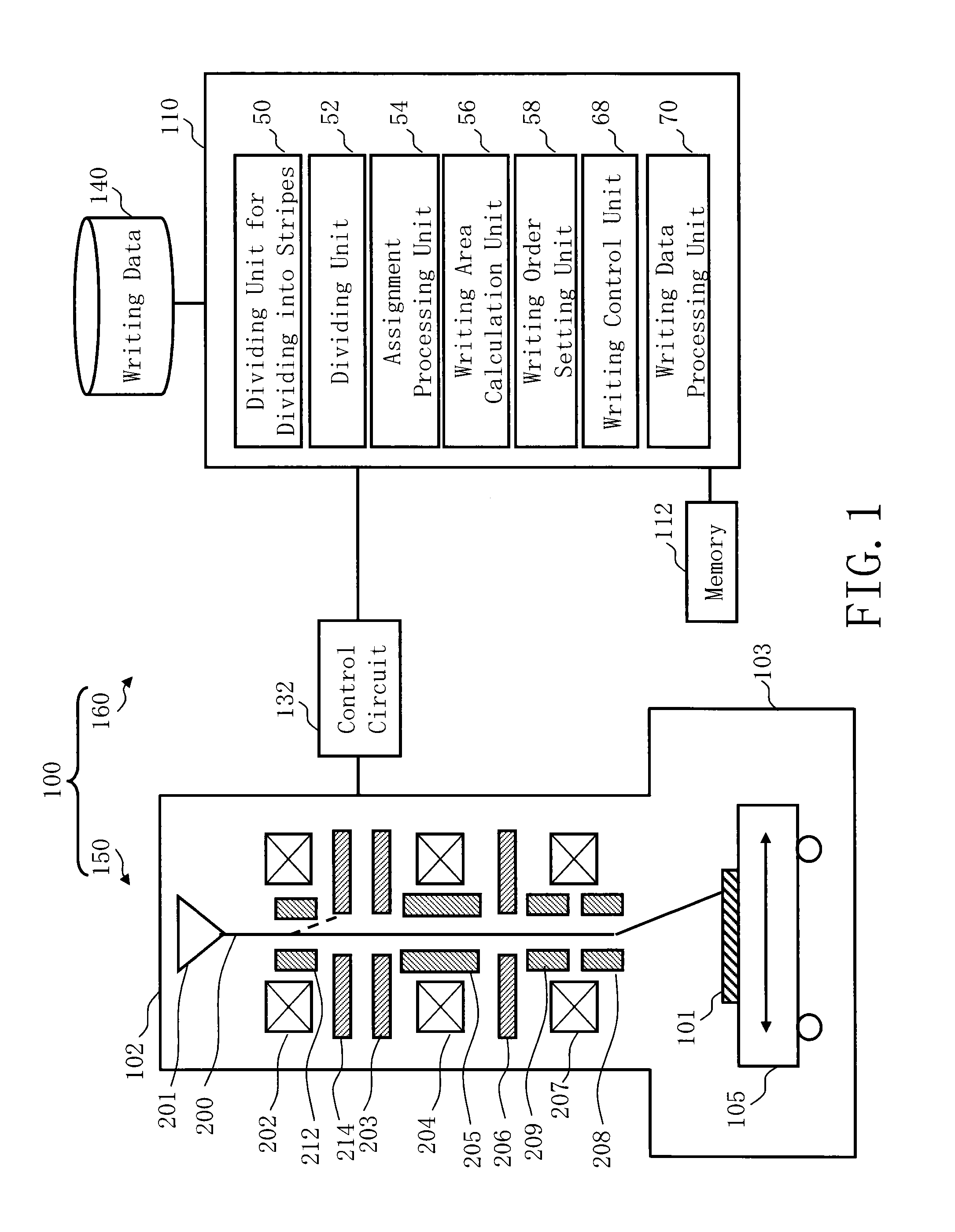
[0037]FIG. 1 is a schematic diagram showing a configuration of a writing apparatus according to the first embodiment. As shown in FIG. 1, a writing (or “drawing”) apparatus 100 includes a writing unit 150 and a control unit 160. The writing apparatus 100 is an example of a charged particle beam writing apparatus. Particularly, it is an example of a variable shaping type (VSB) writing apparatus. The writing unit 150 includes an electron optical column 102 and a writing chamber 103. In the electron optical column 102, there are arranged an electron gun assembly 201, an illumination lens 202, a blanking deflector 212, a blanking aperture 214, a first aperture member 203, a projection lens 204, a deflector 205, a second aperture member 206, an objective lens 207, a main deflector 208 and a sub-deflector 209. In the writing chamber 103, there is arranged an XY stage 105. On the XY stage 105, a target object or “sample”101 such as a mask serving as a writing target is placed when performi...

second embodiment

[0067]In the second embodiment, there will be described a configuration in which re-division is performed for only a stripe region corresponding to the place where the area (or the number of shots) sharply changes (changing over an acceptable threshold value) between adjacent stripe regions.

[0068]FIG. 8 is a schematic diagram showing the structure of a writing apparatus according to the second embodiment. FIG. 8 is the same as FIG. 1 except that a storage device 142 such as a magnetic disk drive is added, and a stripe setting unit 57, determination units 60, 61, and 69, and a re-dividing unit 62 are arranged instead of the writing order setting unit 58 in the control computer 110. Moreover, the re-dividing unit 62 includes a division number calculation unit 72, an area calculation unit 74, a division width calculation unit 76, and a re-dividing processing unit 78.

[0069]The control computer 110, the memory 112, the control circuit 132, the storage device 140, and the storage device 1...

third embodiment

[0101]In the third embodiment, there will be described a configuration in which the shot cycle of a beam shot is lengthened (extended) at the place where the area (or the number of shots) sharply changes (changing over an acceptable threshold value) between adjacent stripe regions. Particularly, a configuration for extending a settling time will be described in the third embodiment.

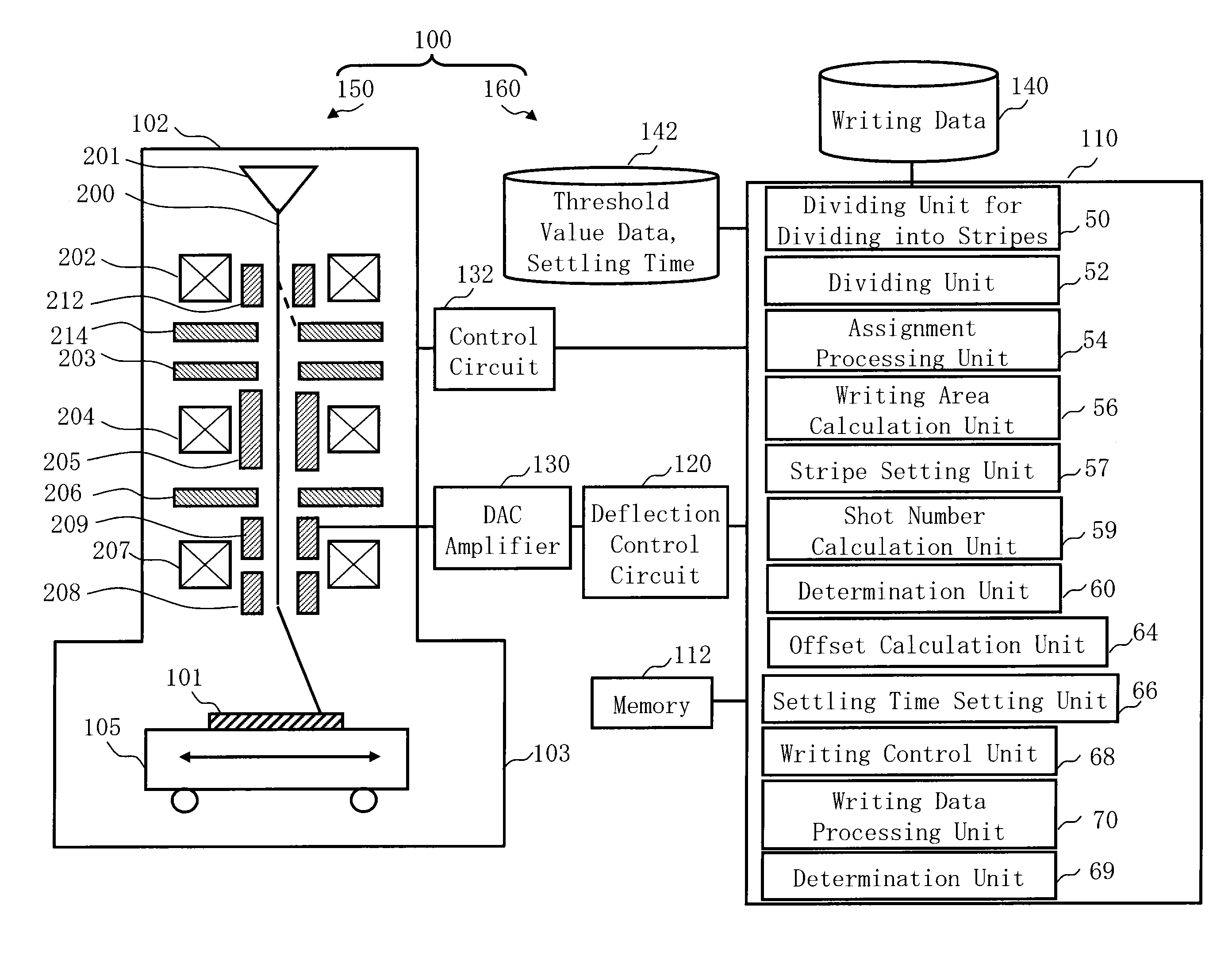
[0102]FIG. 13 is a schematic diagram showing the structure of a writing apparatus according to the third embodiment. FIG. 13 is the same as FIG. 1 except that a deflection control circuit 120, a digital analog conversion (DAC) amplifier unit 130, and a storage device 142 such as a magnetic disk drive are added, and a stripe setting unit 57, a shot number calculation unit 59, determination units 60 and 69, an offset calculation unit 64, and a settling time setting unit 66 are arranged instead of the writing order setting unit 58 in the control computer 110. In the first and second embodiments, although the...


PUM


Abstract

A charged particle beam writing method includes determining whether a difference between one of the total area of a pattern and the number of shots in a stripe region with respect to one of adjacent stripe regions of the stripe regions and one of the total area and the number of shots with respect to the other of the adjacent stripe regions exceeds a threshold value, re-dividing, when the difference exceeds the threshold value, a stripe region where the total area or the number of shots is larger than that of the other stripe region in the adjacent stripe regions so that the difference of the total area or the number of shots becomes lower than or equal to the threshold value, and writing a pattern in the stripe regions including a re-divided stripe region, in the writing order of arrangement of the stripe regions.

Description

CROSS-REFERENCE TO RELATED APPLICATION[0001]This application is based upon and claims the benefit of priority from the prior Japanese Patent Application No. 2013-165885 filed on Aug. 9, 2013 in Japan, the entire contents of which are incorporated herein by reference.BACKGROUND OF THE INVENTION[0002]1. Field of the Invention[0003]The present invention relates to a charged particle beam writing method and a charged particle beam writing apparatus. More specifically, for example, the present invention relates to a method for increasing the accuracy of the writing position of the electron beam writing apparatus.[0004]2. Description of Related Art[0005]The lithography technique that advances miniaturization of semiconductor devices is extremely important as a unique process whereby patterns are formed in semiconductor manufacturing. In recent years, with high integration of LSI, the line width (critical dimension) required for semiconductor device circuits is decreasing year by year. For...

Claims


Application Information

Patent Timeline
IPC IPC(8): H01J37/302H01J37/317
CPCH01J37/3174H01J37/3026H01J2237/31764
Inventor MOTOSUGI, TOMOOANZE, HIROHITONAKAHASHI, SATOSHI
Owner NUFLARE TECH INC
Features
  • R&D
  • Intellectual Property
  • Life Sciences
  • Materials
  • Tech Scout
  • Unparalleled Data Quality
  • Higher Quality Content
  • 60% Fewer Hallucinations
Learn More