Broadband And Wide Field Angle Compensator

a compensator and wide field technology, applied in the field of optical metrology systems, can solve the problems of poor performance, difficult characterization, and increased difficulty in characterization, and achieve the effect of minimizing the coherence

Active Publication Date: 2015-02-26
KLA TENCOR TECH CORP
View PDF5 Cites 8 Cited by
  • Summary
  • Abstract
  • Description
  • Claims
  • Application Information

AI Technical Summary

Benefits of technology

[0023]In yet some other embodiments, a single birefringent plate is cut thin enough, that a zeroth order waveplate can be effectively realized from a single plate of birefringen

Problems solved by technology

As devices (e.g., logic and memory devices) move toward smaller nanometer-scale dimensions, characterization becomes more difficult.
Devices incorporating complex three-dimensional geometry and materials with diverse physical properties contribute to characterization difficulty.
Such an ellipsometer, commonly called a rotating-polarizer or rotating-analyzer ellipsometer, is termed “an incomplete” polarimeter, because it is insensitive to the handedness of the circularly polarized component and exhibits poor performance when the light being analyzed is either nearly completely linearly polarized or possesses a depolarized component.
All of these examples employ relatively thick (on the order of one millimeter) waveplates that are suitable for use with highly collimated light, but are not generally suitable for uncollimated light.
All of these designs are sensitive to field angle and are only suitable for use within an ellipsometer employing highly collimated light.
But, these waveplates are typically thinner than the coherence length of the incident light.
As a result, they suffer from phase and transmittance oscillations as a function of wavelength.
This is a

Method used


Image

  • Broadband And Wide Field Angle Compensator
  • Broadband And Wide Field Angle Compensator
  • Broadband And Wide Field Angle Compensator

Examples


Embodiment Construction

[0033]Reference will now be made in detail to background examples and some embodiments of the invention, examples of which are illustrated in the accompanying drawings.

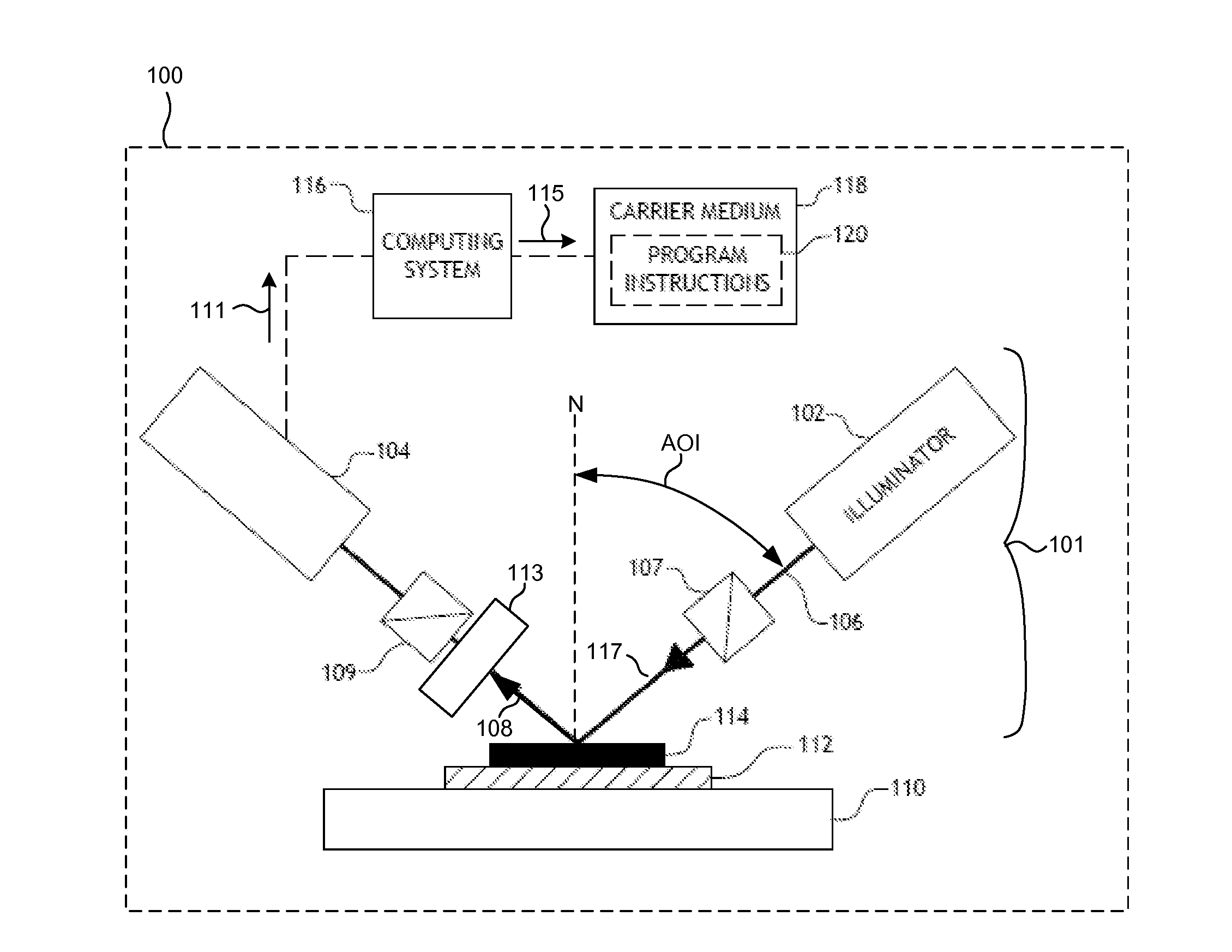
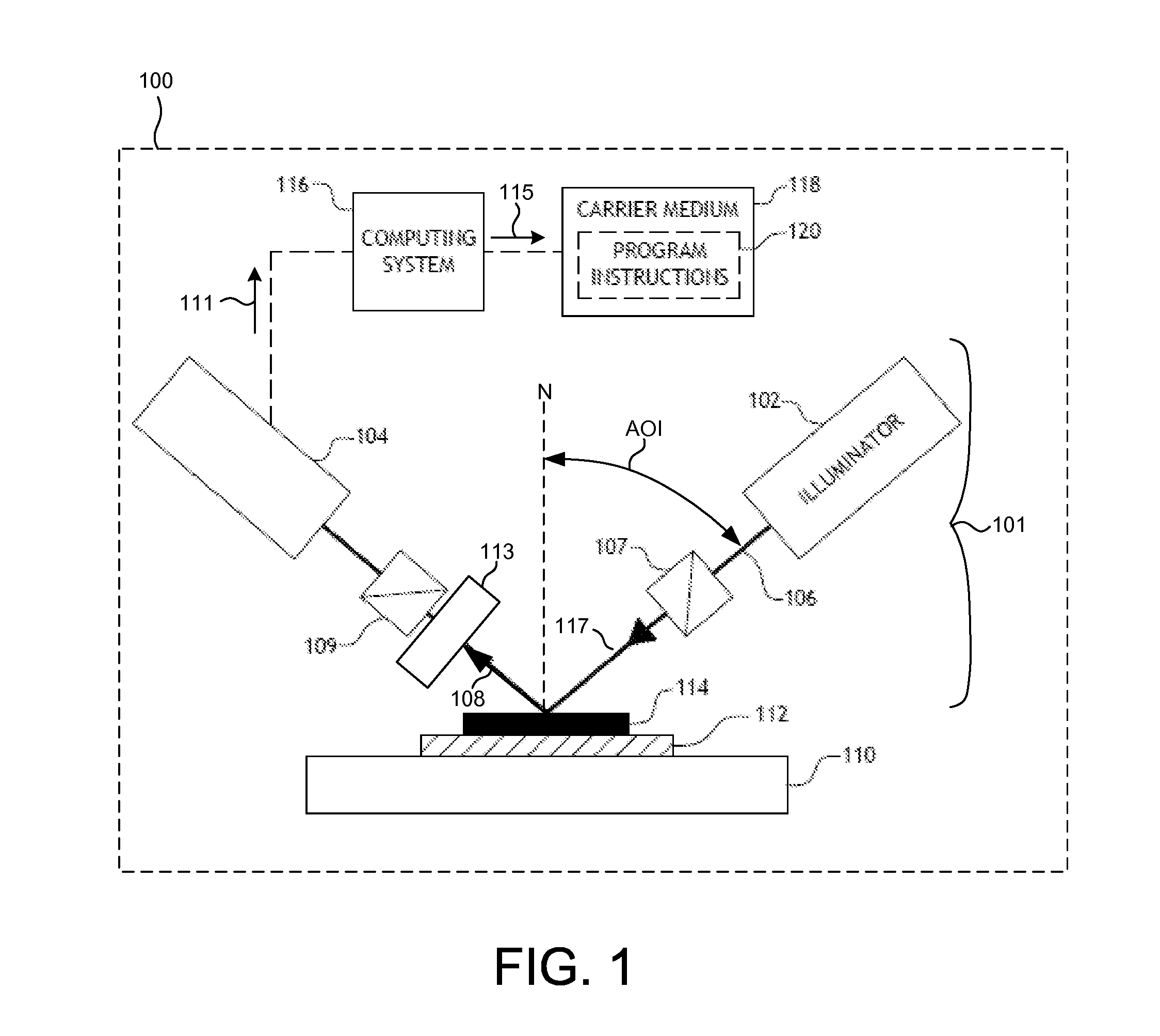
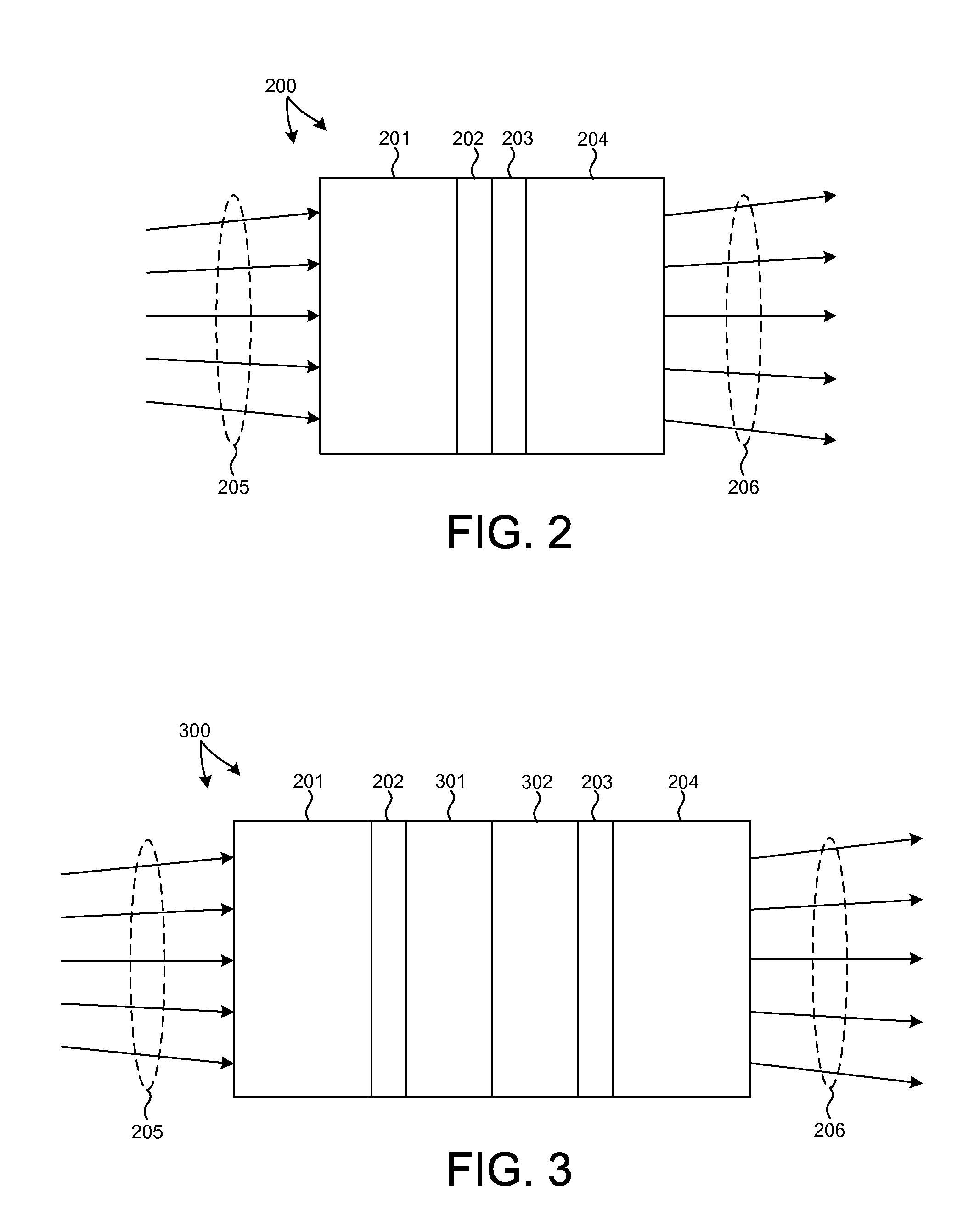
[0034]Rotatable compensators are presented which receive a non-collimated incident beam of light with a broad spectral range including ultraviolet wavelengths, and transform the polarization of the incident light such that the transmitted beam of light acquires a small range of delays across the wavefront. These rotatable compensators may be employed as part of systems configured to measure structural and material characteristics (e.g., material composition, dimensional characteristics of structures and films, etc.). Exemplary systems include ellipsometer or polarimeter systems incorporating a rotating compensator element. By way of example, rotating compensator ellipsometer (RCE) systems, dual rotating compensator (RCRC) systems, rotating polarizer, rotating compensator (RPRC) systems, and rotating compensator, and r...


PUM


Abstract

A rotatable compensator configured to transmit non-collimated light over a broad range of wavelengths, including ultraviolet, with a high degree of retardation uniformity across the aperture is presented. In one embodiment, a rotatable compensator includes a stack of four individual plates in optical contact. The two thin plates in the middle of the stack are made from a birefringent material and are arranged to form a compound, zeroth order bi-plate. The remaining two plates are relatively thick and are made from an optically isotropic material. These plates are disposed on either end of the compound, zeroth order bi-plate. The low order plates minimize the sensitivity of retardation across the aperture to non-collimated light. Materials are selected to ensure transmission of ultraviolet light. The optically isotropic end plates minimize coherence effects induced at the optical interfaces of the thin plates.

Description

CROSS REFERENCE TO RELATED APPLICATION[0001]The present application for patent claims priority under 35 U.S.C. §119 from U.S. provisional patent application Ser. No. 61 / 869,065, entitled “Broadband and Wide Field Angle Compensator,” filed Aug. 23, 2013, the subject matter of which is incorporated herein by reference in its entirety.TECHNICAL FIELD[0002]The described embodiments relate to optical metrology systems, and more particularly to systems including rotatable compensator elements.BACKGROUND INFORMATION[0003]Semiconductor devices such as logic and memory devices are typically fabricated by a sequence of processing steps applied to a specimen. The various features and multiple structural levels of the semiconductor devices are formed by these processing steps. For example, lithography among others is one semiconductor fabrication process that involves generating a pattern on a semiconductor wafer. Additional examples of semiconductor fabrication processes include, but are not l...

Claims


Application Information

Patent Timeline
IPC IPC(8): G02B5/30G01N21/21G01J1/42
CPCG02B5/3083G01J1/429G01N2201/068G01N2021/213G01N21/211G02B5/3091G02F1/13363G01N21/23G01N21/9501
Inventor ROTTER, LAWRENCEFLOCK, KLAUSARAIN, MUZAMMILWANG, DAVID Y.
Owner KLA TENCOR TECH CORP
Why Eureka
Try Eureka