Self mode-locking semiconductor disk laser

Active Publication Date: 2015-03-05
SOLUS TECH
View PDF13 Cites 5 Cited by
  • Summary
  • Abstract
  • Description
  • Claims
  • Application Information

AI Technical Summary

Benefits of technology

[0034]The astigmatism may be introduced to the cavity mode by rotating the fourth mirror so as to increase the angle of incidence of a resonating field upon the fourth mirror.
[0035]The method of self mode locking a laser may further comp

Problems solved by technology

As a result, the above described solid state ultrafast lasers are relatively complex, bulky, have high maintenance requirements and most significantly are expensive to produce.
The main drawback of systems that employ SESAMs is that they are still relatively complex to produce and maintain.
Although average powers of up to 500 mW have been demonstrated, systems based on such materials are often limited in their ability to sufficiently scale their average power.
They are however limited to operating at wavelengths around 1030 nm and 1550 nm and the second harmonics produced from these fundamental wavelengths.
Within semiconductor lasers with amplification schemes e.g. gain-switched sources based

Method used


Image

  • Self mode-locking semiconductor disk laser
  • Self mode-locking semiconductor disk laser
  • Self mode-locking semiconductor disk laser

Examples


Example

[0078]In the description which follows, like parts are marked throughout the specification and drawings with the same reference numerals. The drawings are not necessarily to scale and the proportions of certain parts have been exaggerated to better illustrate details and features of embodiments of the invention.

DETAILED DESCRIPTION

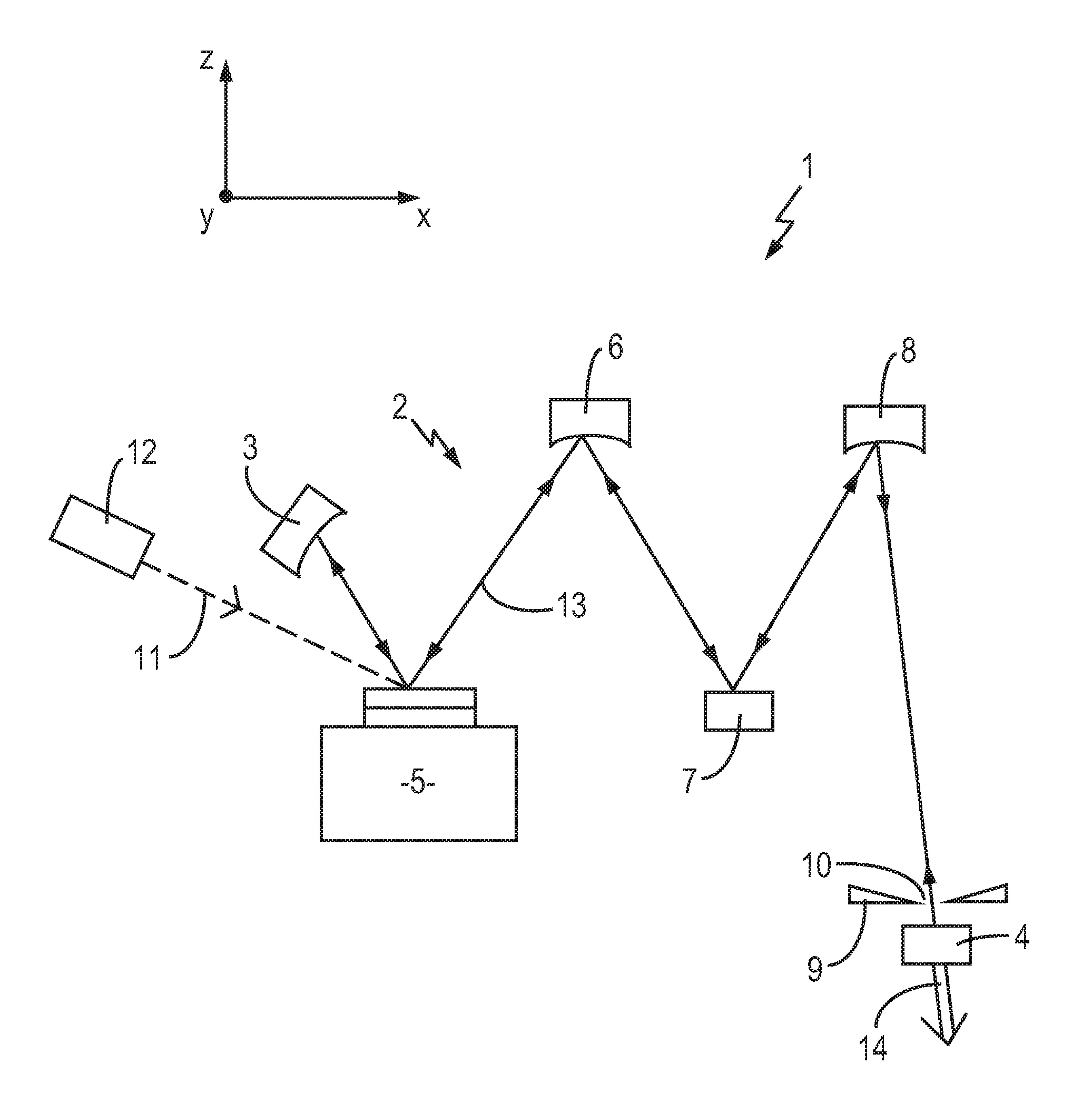
[0079]Referring initially to FIG. 1, a schematic representation of a self mode-locking, external-cavity surface-emitting, semiconductor laser 1 in accordance with an embodiment of the present invention is shown. For clarity of understanding axes are provided within this figure. The plane of the cavity referred to below is the plane defined by the x and z axes.

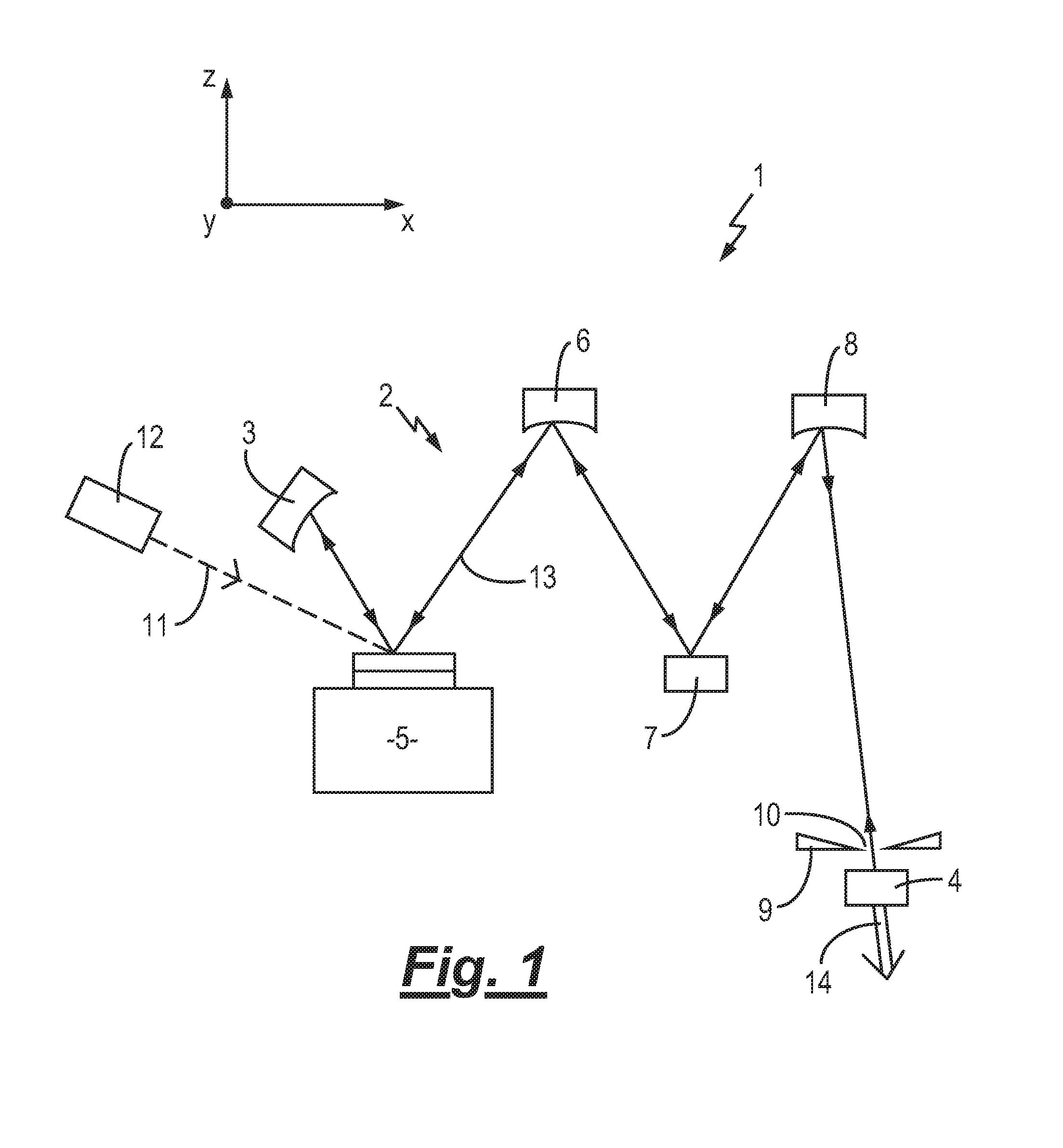
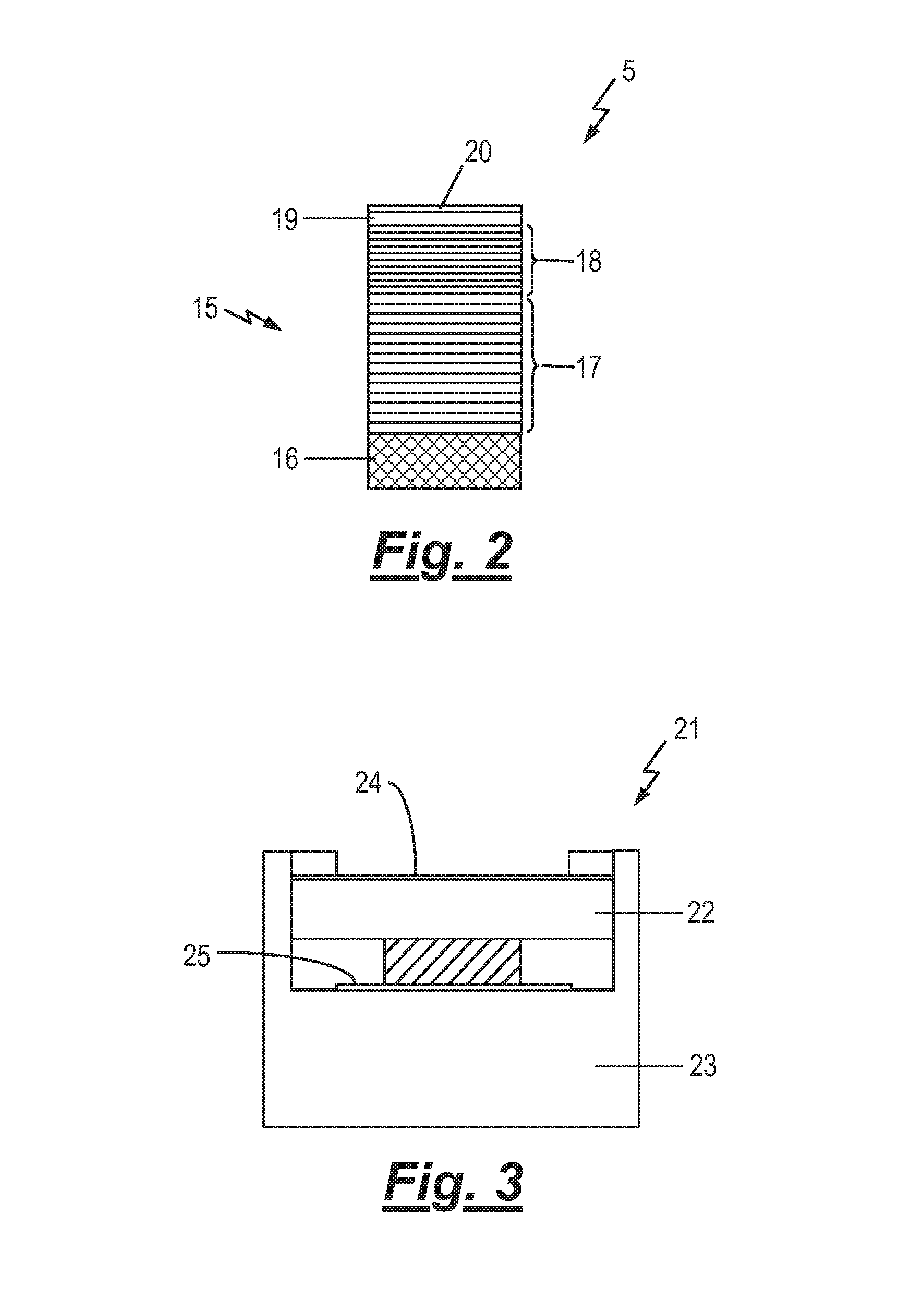
[0080]The self mode-locking laser 1 can be seen to comprise a laser-resonator 2 formed between a first 3 and a second mirror 4 and includes a multilayer, optically-pumped, semiconductor disk laser (SDL) 5 further details of which are provided below with reference to FIGS. 2 and 3. As can be seen the S...


PUM


Abstract

The present invention describes a self mode locking laser and a method for self mode locking a laser. The laser (1) comprises a resonator terminated by first (3) and second (4) mirrors and folded by a third mirror (5). The third mirror comprises a single distributed Bragg reflector (17) upon which is mounted a multilayer semiconductor gain medium (18) and which includes at least one quantum well layer and an optical Kerr lensing layer (22). Self mode locking may be achieved by configuring the laser resonator such that the lensing effect of the Kerr lensing layer acts to reduce an astigmatism deliberately introduced to the cavity mode. The self mode locking of the laser may be further enhanced by selecting the length of the resonator such that a round trip time of a cavity mode is matched with an upper-state lifetime of one or more semiconductor carriers located within the gain medium.

Description

[0001]The present invention relates to the field of semiconductor lasers and in particular to a semiconductor disc laser (SDL) configured to emit ultra short pulses of radiation.[0002]It is noted that SDLs are also known in the art as Vertical External Cavity Emitting Lasers (VECSELs) or Optically Pumped Semiconductor Lasers (OPSLs). Therefore the term semiconductor disc laser (SDL) when used throughout the present description is used to refer to each of these systems.[0003]The term “ultra short” pulses as used within the following description refers to pulses having a duration from about 100 picoseconds (ps) down to a few femtoseconds (fs).[0004]Ultra short pulses of optical radiation generated by laser sources are employed in a range of scientific, instrumentation and nonlinear optics applications. One particular application for these ultra short pulses is in the field of nonlinear microscopy for example Two-Photon Excited Fluorescence (TPEF) microscopy or other similar multi-phot...

Claims


Application Information

Patent Timeline
IPC IPC(8): H01S5/22H01S5/065
CPCH01S5/065H01S5/2228H01S3/0805H01S3/0813H01S3/0816H01S3/094053H01S3/1112H01S5/02484H01S5/041H01S5/0657H01S5/141H01S5/183H01S3/0941H01S5/18H01S5/34
Inventor HAMILTON, CRAIG JAMESMALCOLM, GRAEME PETER ALEXANDERKORNASZESKI, LUKASZ
Owner SOLUS TECH
Why Eureka
Try Eureka