

Method and apparatus for processing sample material
a sample material and method technology, applied in the field of method and apparatus for processing sample materials, can solve the problems of inability to achieve effective doses of sonic energy, inability to control the effect of ultrasonics, and inability to provide an automated, broad range, precise material processing or reaction control mechanism. to achieve the effect of enhancing the effect of irradiation
- Summary
- Abstract
- Description
- Claims
- Application Information
AI Technical Summary
Benefits of technology
Problems solved by technology
Method used
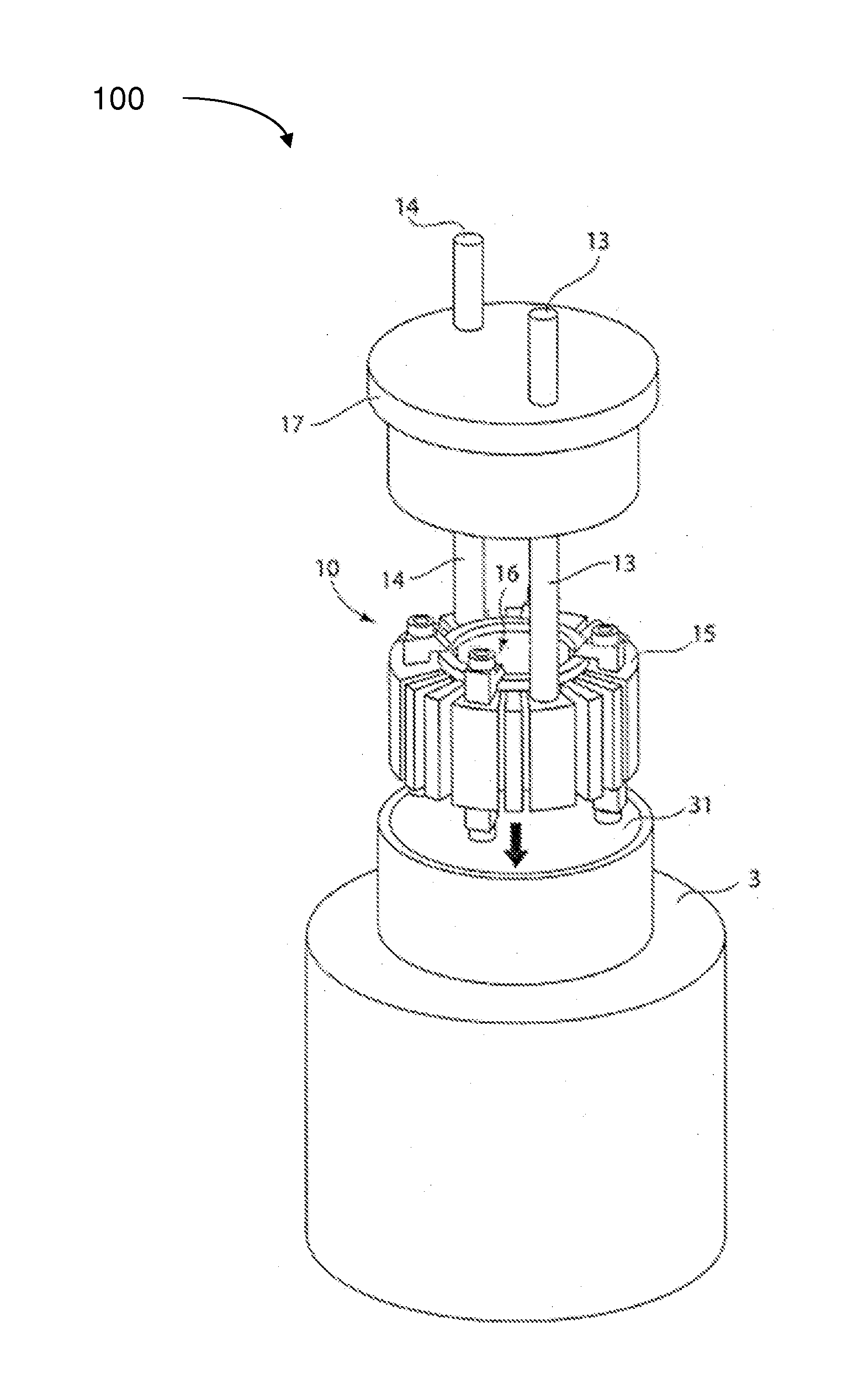
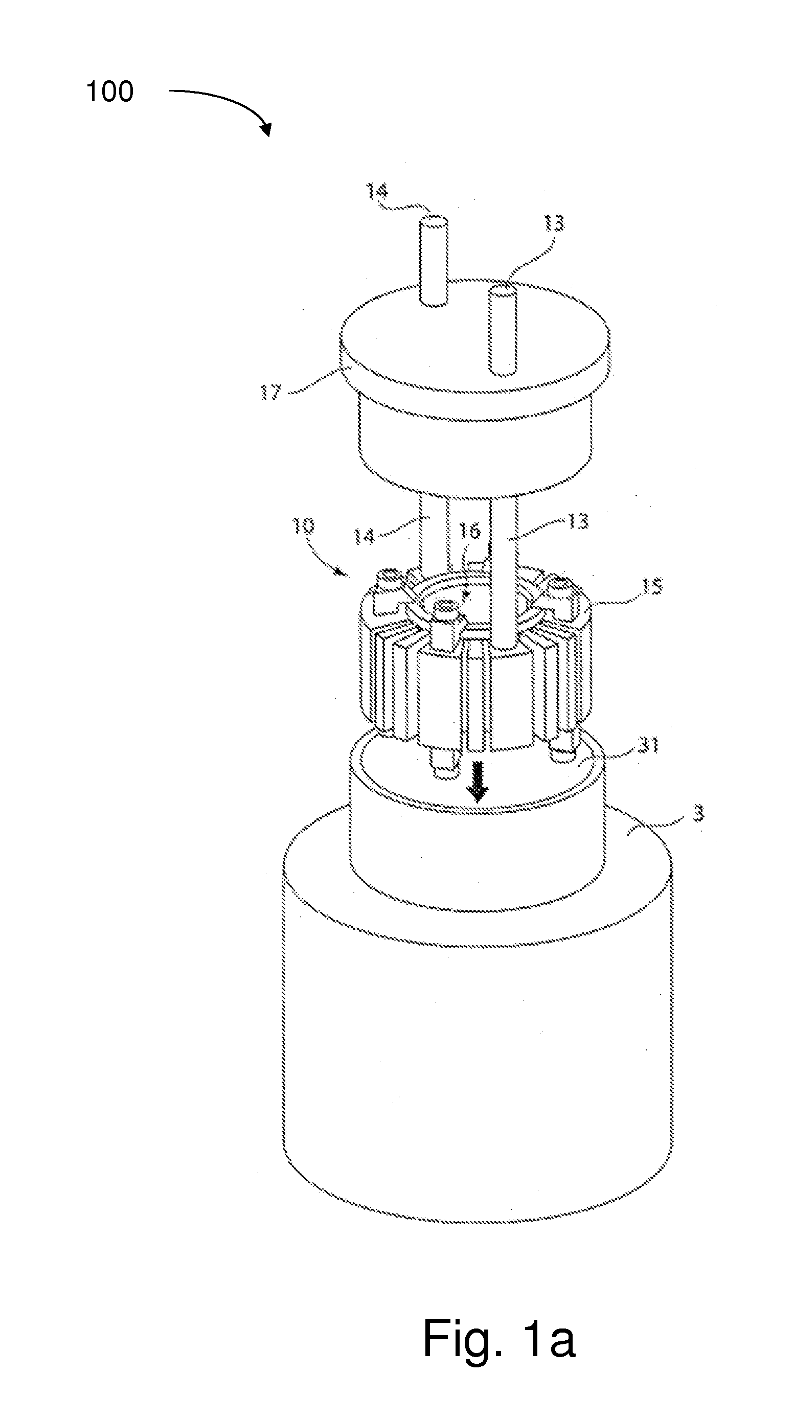
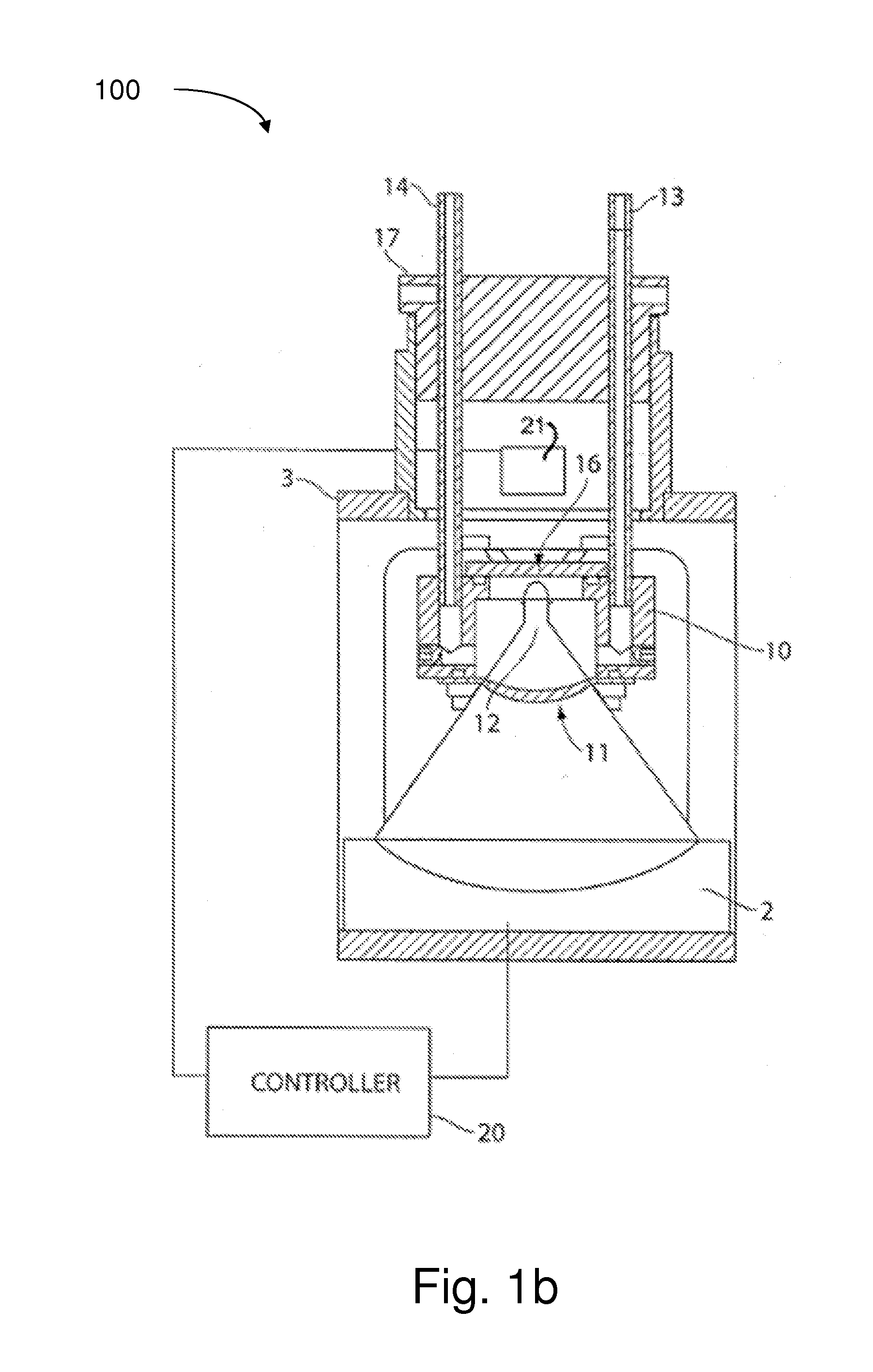
Image

Examples
Embodiment Construction
[0050]“Sonic energy” as used herein is intended to encompass such terms as acoustic energy, acoustic waves, acoustic pulses, ultrasonic energy, ultrasonic waves, ultrasound, shock waves, sound energy, sound waves, sonic pulses, pulses, waves, or any other grammatical form of these terms, as well as any other type of energy that has similar characteristics to sonic energy. “Focal zone” or “focal point” as used herein means an area where sonic energy converges and / or impinges on a target, although that area of convergence is not necessarily a single focused point, but may include a volume of varying size and shape. As used herein, the terms “process chamber,”“processing chamber” or “processing zone” as used herein means a vessel or region where the sonic energy converges, and the sample material is present for treatment. As used herein, “nonlinear acoustics” can mean lack of proportionality between input and output. For example, as the amplitude applied to the acoustic transducer incr...
PUM
| Property | Measurement | Unit |
|---|---|---|
| Length | aaaaa | aaaaa |
| Width | aaaaa | aaaaa |
| Frequency | aaaaa | aaaaa |
Abstract
Description
Claims
Application Information