Process and Apparatus for producing Hydrocarbon Fuel from Waste Plastic

a technology of hydrocarbon fuel and process equipment, which is applied in the direction of lighting and heating equipment, indirect heat exchangers, organic chemistry, etc., can solve the problems of high operating cost, high capital investment and high operating cost of the 2-step cracking process, and the inherent catalyst deactivation over time by coke formation, so as to prevent coke build-up, increase yield, and high quality

Active Publication Date: 2015-03-19
VIRENS ENERGY LLC
View PDF5 Cites 48 Cited by
  • Summary
  • Abstract
  • Description
  • Claims
  • Application Information

AI Technical Summary

Benefits of technology

[0024]The invention further provides a system for producing continuously hydrocarbon oil from residential and industrial waste plastic comprising: a dryer unit to dry the mixed waste plastic to less than 1% moisture and to preheat the plastic, a melt screw reactor to melt the waste plastic at about 290-325° C. while any PVC decomposes and removing the formed HCl gas prior to the pyrolysis, a pumping screw to pump the liquid plastic into the pyrolysis unit, a pyrolysis reactor to thermally decompose the waste plastic at about 400-600° C. into hydrocarbons whereby the hydrocarbon gas exits the pyrolysis reactor through a plurality of vapor vents located at the top section of the pyrolysis reactor, a catalytic treatment unit comprising a transition metal insert through which the hydrocarbon gas passes to further decompose long chain hydrocarbons, a gas purifying unit, wherein the hydrocarbon gas is chemically treated to remove any acid and sulfur components, comprising a dry spray alkali injection treatment unit and a ceramic filter system, a condensing unit comprising a plurality of condensers operated at various temperatures to fractionate the hydrocarbon gas, into heavy oil, middle distillate and light-range, a thermal oxidizer to destroy any VOCs from the non-condensable hydrocarbons and the scrubber units, a first cooling screw connected to the discharging end of the pyrolysis reactor to safely remove any ash, and a second cooling screw connected to the discharging end of the gas purifier unit to remove inorganic solids. The system further comprises a ball bearing screw auger connected to the discharging and feeding end of the pyrolysis reactor to continuously recycle ball bearings together with the liquid plastic through the pyrolysis reactor to prevent coke build-up and aides in heat transfer.
[0025]According to the present invention, the process for producing hydrocarbon oil from thermal decomposition of waste plastic provides an improved process producing high quality hydrocarbon oil with increased yields compared to the prior art. Moreover, the process provides an economical, robust and flexible process to allow easy adjustment of process parameters based on waste plastic properties and composition. Furthermore, the pyrolysis process and apparatus provide an off-gas treatment with a greater than 99% removal rate of any chlorine and sulfur components and a more efficient utilization of recycled heat energy.

Problems solved by technology

The 2-step cracking process requires high capital investment and high operating cost.
Another disadvantage is the use of a catalyst and the inherent catalyst deactivation over time by coke formed during the high temperature of the second cracking reaction.
Furthermore, the cracking reaction is prone to coke formation which reduces the hydrocarbon formation rendering the 2-step cracking process less efficient for making high grade hydrocarbon oil from waste plastic.
A common problem with thermal decomposition of waste plastic is the coke formation in the reaction vessel which reduces the heat conductivity.
Liquid heat transfer media suffer from increasing the heat conductivity by only small increments that may not reduce significantly the coke formation.
Another drawback for using a liquid heat transfer medium is the consumption during the high pyrolysis temperature which requires substitution of liquid heat transfer medium over time with make-up material.
As a result, the hydrocarbon vapors formed are subjected to the high pyrolysis temperature along the entire length of the reactor leading to an increase in residence time of the hydrocarbon vapors.
Furthermore, the hydrocarbon vapors are subjected to extended exposure of high temperature which in turn produces more non-condensable hydrocarbon gas and thus lowers the value of hydrocarbon fuel.
The time until the waste plastic reaches the decomposition temperature requires more energy, increases the residence time and renders the process less efficient reducing the yield for the desired hydrocarbon oil including the middle distillate and light-range hydrocarbons.

Method used


Image

  • Process and Apparatus for producing Hydrocarbon Fuel from Waste Plastic
  • Process and Apparatus for producing Hydrocarbon Fuel from Waste Plastic
  • Process and Apparatus for producing Hydrocarbon Fuel from Waste Plastic

Examples


example 1

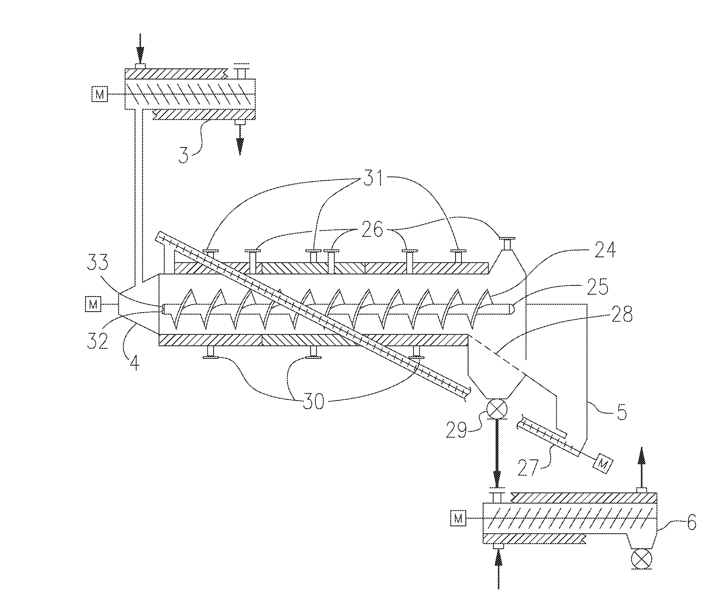
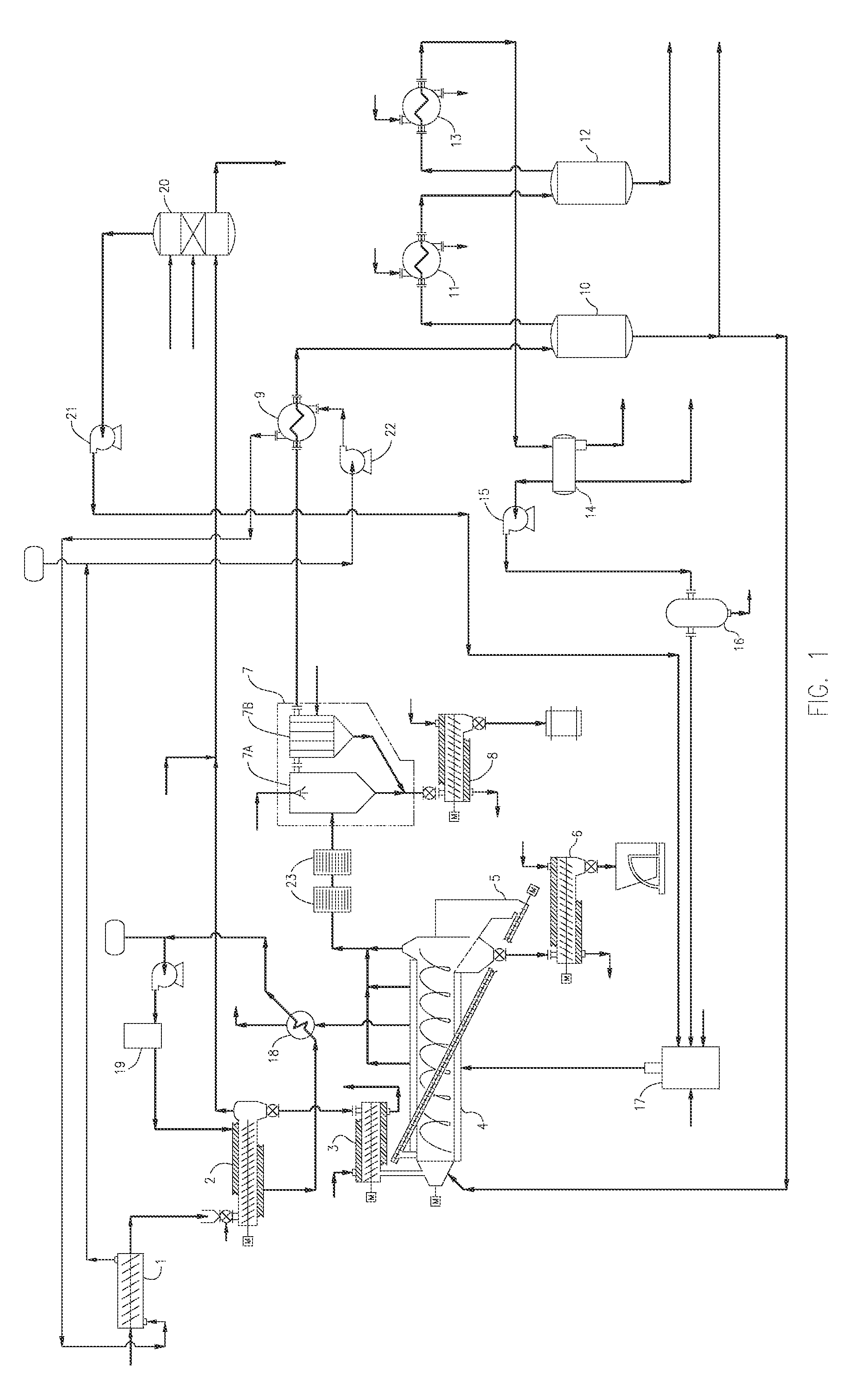
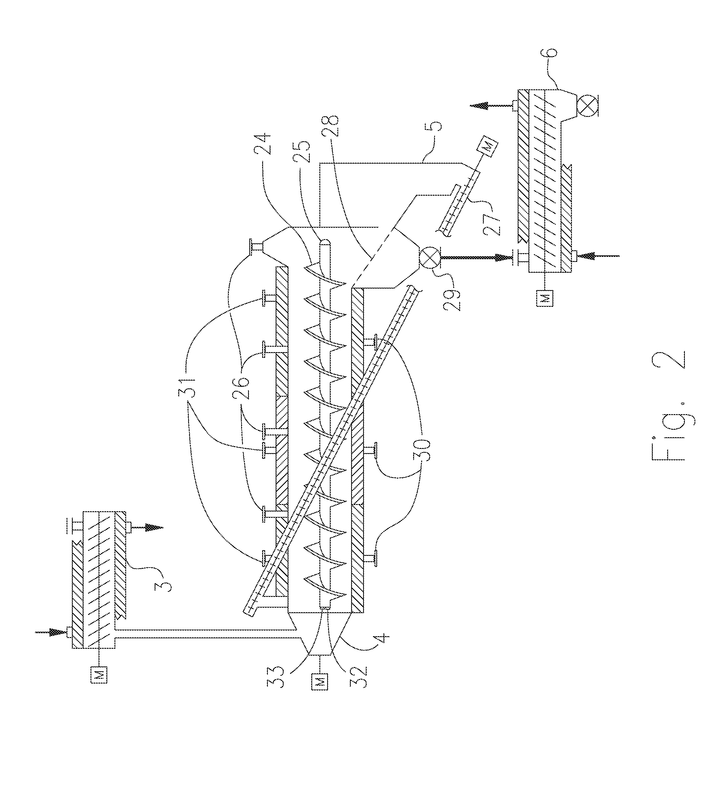
[0060]A simulation of the process using a commercial plant design was performed based on the process shown in FIG. 1 and the pyrolysis reactor 4 as shown in FIG. 2. The thermal decomposition process and reactor 2 are designed to continuously process 25 tons per 24 hours of waste plastic or 2296 lb / hr mixed plastic feedstock. The composition of the plastic feedstock is 45 wt % LDPE, 49 wt % PP, 2 wt % HDPE, and 0.25 wt % PS, 0.35 wt % PVC, 0.1% PET, and 3 wt % other plastics, as outlined in Table 1.

TABLE 1Hydrocarbon Product and Recycled Streams produced in thermaldecomposition calculated for a typical waste plastic feedstockWastePlasticFeedFeed StreamFeedstockComposition %lb / hrPP491132LDPE451033HDPE246PET0.12PVC0.358PS0.256other369

[0061]The pyrolysis reactor 4 is 25 feet long and has a diameter of 2.5 feet. The mixed waste plastic has a moisture content of about 10% by weight. The waste plastic is shredded into pieces of about 2 inches by 2 inches and fed into a dryer and heated to ...


PUM

PropertyMeasurementUnit
temperatureaaaaaaaaaa

Abstract

A process and apparatus for producing hydrocarbon oil from the thermal decomposition of waste plastics in a continuous process which comprises melting of a waste plastic feedstock into an auger assisted melt reactor to remove chlorine and organics contained in the waste plastic, and transferring the melted waste plastic into an heated screw pyrolysis reactor which includes a transitional metal heat transfer medium. The hydrocarbon gas from the pyrolysis reactor is fed into a vessel containing metal trays for a second decomposition which is connected with an alkali treatment 2-step process gas reactor to remove acidic gases, and any inorganic solids. The hydrocarbon gases are separated by three separate condensers. The hydrocarbon fraction of the first condenser is recycled back into the pyrolysis reaction for further thermal treatment, and the hydrocarbon fractions are collected in the remaining condensers.

Description

[0001]The present application claims the benefits of the U.S. Provisional Application Ser. No. 61 / 877,311, filed Sep. 13, 2013 which is herein incorporated by reference in its entirety.FIELD OF INVENTION[0002]The present invention is directed to a process and apparatus for producing liquid fuel from residential and industrial waste plastic, and in particular, to a process and apparatus for producing continuously high quality grade liquid hydrocarbon fuel from residential and industrial waste plastic by thermal and catalytic decomposition in an indirectly heated screw reactor.BACKGROUND OF THE INVENTION[0003]Waste plastic from municipal and industrial sources is continuously increasing. In the U.S., the amount of plastic waste produced in 2010 was 31 million tons, an increase of 25% in ten years. Only 8 percent of the total plastic waste generated in 2010 was recovered for recycling. Waste plastic represents a considerable part of municipal wastes. Over 78 wt % of the total municipal...

Claims


Application Information

Patent Timeline
Patent Type & Authority Applications(United States)
IPC IPC(8): C10G1/10B01J19/20
CPCC10G1/10B01J2219/00761B01J19/20C10G1/02C10G19/00
Inventor GEPHART, STEPHEN B.HILL, JOHN C.
Owner VIRENS ENERGY LLC
Why Eureka
Try Eureka