Phase Contrast Microscopy With Oblique Back-Illumination

a contrast microscopy and phase contrast technology, applied in the field of tissue pathology assessment, can solve the problems of inability to fully represent tissue biopsies, requiring hours or days to provide, and requiring hours or days to provide, and achieve the effect of in-vivo endomicroscopy applications

Inactive Publication Date: 2015-03-26
TRUSTEES OF BOSTON UNIV
View PDF6 Cites 38 Cited by
  • Summary
  • Abstract
  • Description
  • Claims
  • Application Information

AI Technical Summary

Benefits of technology

[0012]This disclosure describes a new phase contrast technique, sometimes referred to herein as oblique back-illumination microscopy (OBM). OBM works in a reflected light geometry (sometimes called epi-detection geometry), and is thus amenable to in-vivo endomicroscopy applications, among many others. OBM requ

Problems solved by technology

For example, the process is laborious and time consuming, requiring hours or days to provide results.
For another example, tissue biopsies only provide a sparse sampling that may not be fully representative of the region of interest.
For another example, tissue biopsies pose a risk of infection and/or other complications to the patient and can cause discomfort.
Nonetheless, efforts to develop optical biopsy techniques and equipment have had a limited success.
None of these techniques is particularly quantitative in the sense that the measured signal cannot be easily converted into a measured phase.
The application of these techniques is limited, however, because each one works only in the transmission direction.
This feature limits the use of these techniques to use with a transmission light source.
A difficulty

Method used


Image

  • Phase Contrast Microscopy With Oblique Back-Illumination
  • Phase Contrast Microscopy With Oblique Back-Illumination
  • Phase Contrast Microscopy With Oblique Back-Illumination

Examples


example 1

Monte Carlo Analysis of OBM

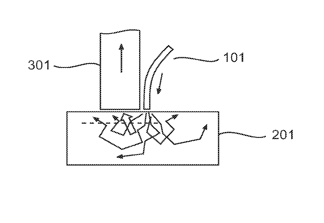
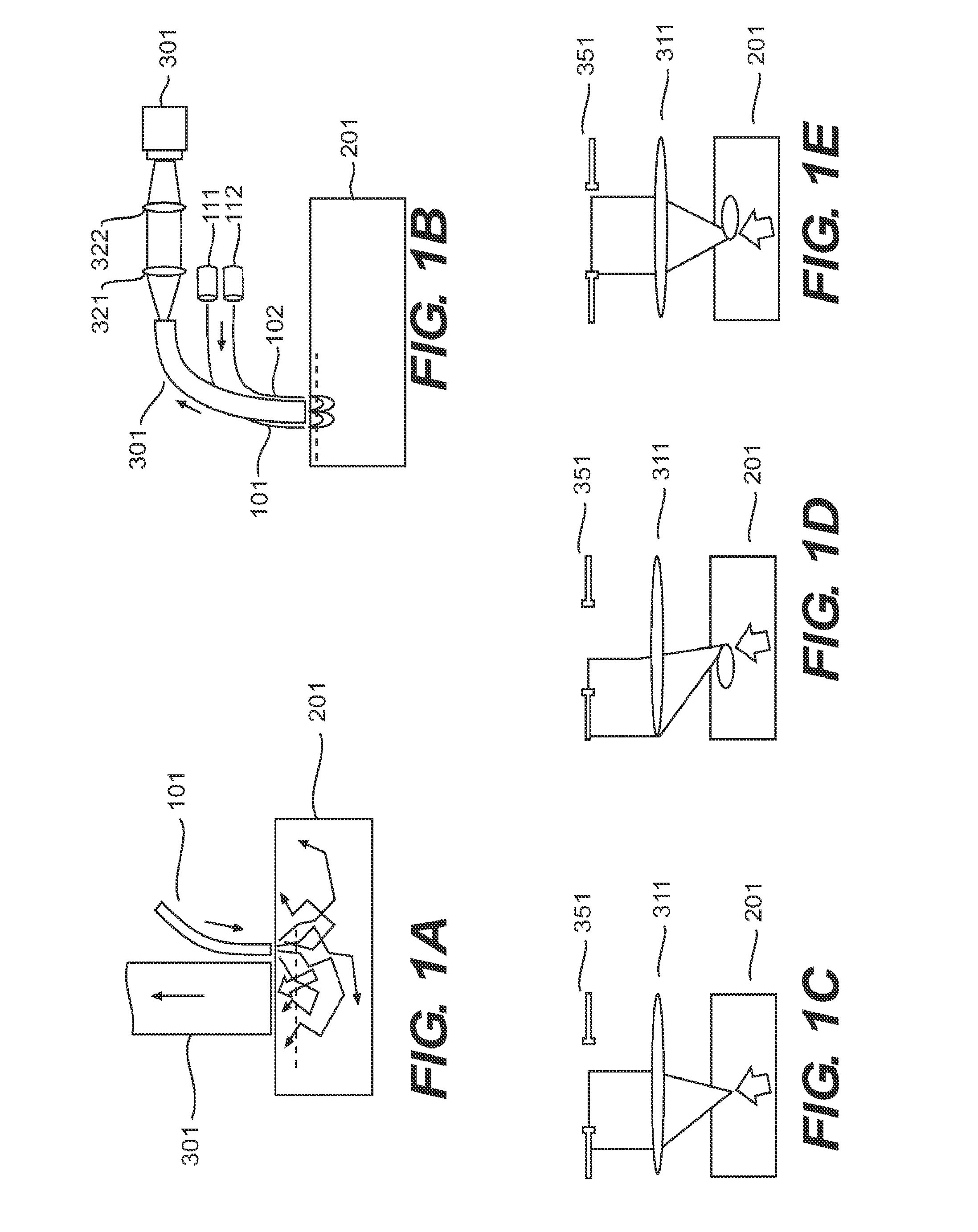
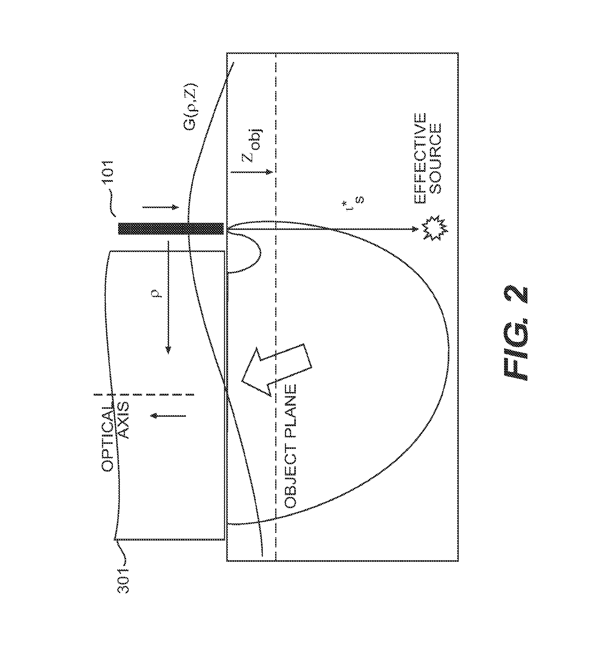
[0150]As described herein, OBM uses an off axis light source. Illumination light that is multiply scattered in the object is re-directed toward the sample surface and is detected. In this manner, the object plane (defined as the plane that is in focus with respect to the detection optics), is back-illuminated. Because the illumination source is off-axis, the back-illumination flux at the object plane is directed, on average, not quite vertically but with a slight tilt away from the illumination source. That is, the back-illumination is oblique. The illumination source is mimicked by an effective virtual source a distance l*s directly below it (l*s being the transport scattering length of the medium) (FIG. 2). The overlap of the illumination and detection spread functions of the illuminating and detected light is referred to as a “photon banana”. Understanding the distribution of photons in this system will help characterize the geometrical constraints of O...

example 2

OBM Images of Onion Skin

[0155]To demonstrate the resolution and image quality of the OBM technique, images of onion skin were acquired with a flexible endomicroscope configuration. (FIG. 3.) The endomicroscope setup is based on the use of a flexible fiber-bundle probe containing 30,000 fibers. One probe variant provides a 600 μm field-of-view with 6.5 μm resolution. Another probe variant provides a 240 μm field of view with 2.5 μm resolution. The outer diameter of both probes is 2.8 mm. Imaging depth is 70 μm. Illumination is provided by LEDs, and there are no moving parts. The frame rate of the system is 17 Hz.

[0156]Panels (a) and (b) of FIG. 3 are raw images acquired with left and right illumination. Panel (c) is an absorption image (a+b). Panel (d) is a phase gradient image (a- b). Note that panel (d) contains negative values, meaning its zero level is gray. Note that the difference and sum images are very different despite having been obtained simultaneously with the same raw da...

example 3

Images of rodent Colon

[0157]To further demonstrate the resolution and image quality of the OBM technique, as well as to demonstrate its clinical relevance, images of the exposed surface of an excised and fixed rat colon were obtained using the endomicroscope setup described in Example 2. FIGS. 9a and 9b were obtained with left and right illumination, respectively, after core removal (raw core artifacts shown in insets). It is difficult to make out structure without core removal. FIGS. 9c and 9d are the resulting sum (absorption) and difference (phase gradient) images. Both images highlight manifestly different information. In particular, colonic crypts are clearly apparent.


PUM


Abstract

A method of creating a phase contrast image is provided. In some embodiments the method comprises illuminating the target region of a sample with a first light source to provide a first oblique back illumination of the target region of the sample, and detecting a first phase contrast image from light originating from the first light source and back illuminating the target region of the sample. In some embodiments the method further comprises illuminating the sample with a second light source to provide a second oblique back illumination of the target region of the sample, and detecting a second phase contrast image from light originating from the second light source and back illuminating the target region of the sample. In some embodiments a difference image of the target region of the sample is created by subtracting the second phase contrast image of the target region of the sample from the first phase contrast image of the target region of the sample. Apparatus for carrying out the methods are also provided. The methods and apparatus find use, for example, in endoscopy.

Description

CROSS-REFERENCE TO RELATED APPLICATIONS[0001]This application claims priority to U.S. Provisional Application No. 61 / 617,707, filed Mar. 30, 2012, which is hereby incorporated herein by reference.GOVERNMENT FUNDING[0002]This invention was made with Government Support under Contract No. EB010059 awarded by the National Institutes of Health. The Government has certain rights in the invention.INTRODUCTION[0003]The standard technique to assess tissue pathology in clinical applications is to perform a biopsy [1]. In general, assessment is made based on purely morphological considerations. The technique often involves use of a device to observe tissue with high resolution. As successful and prevalent as this biopsy procedure has become, it faces certain drawbacks. For example, the process is laborious and time consuming, requiring hours or days to provide results. For certain applications it would be useful to have an alternative procedure that, in some embodiments, requires less time and...

Claims


Application Information

Patent Timeline
IPC IPC(8): G06T5/00G02B21/00A61B1/00G01N21/25A61B1/04G02B21/06G01N21/27
CPCG06T5/009G02B21/06G02B21/0012G01N21/27G01N21/255A61B1/04G06T2207/20221A61B1/00172G01N2201/062G01N2201/0866G06T2207/10068G06T2207/20208A61B1/00009G02B21/14G01N21/4795G01N2021/4797A61B1/044A61B1/000095
Inventor MERTZ, JEROME CHARLESFORD, TIMOTHY NEHILEYCHU, KENGYEH KEN
Owner TRUSTEES OF BOSTON UNIV
Why Eureka
Try Eureka