Self-diagnosing method for diagnosing a scr system

a catalytic reduction and self-diagnosing technology, applied in the direction of machines/engines, electrical control, exhaust treatment electric control, etc., can solve the problems of high nox level, inability to achieve high efficiency, and increase in particulates, so as to reduce the reliability and accuracy of self-diagnosing method, accurate measurement of nox emission level entering and leaving, and accurate diagnosis of scr nox conversion efficiency

Active Publication Date: 2015-04-30
VOLVO LASTVAGNAR AB
View PDF6 Cites 15 Cited by
  • Summary
  • Abstract
  • Description
  • Claims
  • Application Information

AI Technical Summary

Benefits of technology

[0040]diagnosing NOx measurement performance of said first and second exhaust gas sensors on the basis of said registered sensor output. By means of the two exhaust gas sensors, one positioned on each side of the SCR catalyst, a very accurate measurement of the NOx emission level entering and leaving the SCR catalyst may be determined, thereby facilitating an accurate diagnose of the SCR NOx conversion efficiency. Without a gas exhaust sensor upstream the SCR catalyst, the NOx emission level entering the SCR catalyst must be estimated, thereby reducing the reliability and accuracy of the self-diagnosing method.
[0041]The method may include an initial step of controlling that an exhaust gas temperature of said SCR system exceeds a predetermined temperature level. Thereby any fluctuations in engine NOx emission values, and / or exhaust gas sensor measurement performance, and / or SCR conversion efficiency can be eliminated. Furthermore, the NOx catalyst requires that the temperature is above about 200° C. to fully operate in the third test sequence.

Problems solved by technology

Said high efficiency is however only possible at an elevated combustion temperature at which high NOx levels are inevitable.
Moreover, a suppression of NOx formation by internal means (airfuel ratio) has the tendency to cause an increase in particulates, known as the NOx-particulates trade off.
Reducing the oxides of nitrogen (NO and NO2, referred to as NOx) and particulate matter (PM) in exhaust gases from a diesel engine has become a very important problem in view of the protection of environment and the saving of finite fossil energy supply.
Vehicles equipped with diesel or other lean burn engines offer the benefit of increased fuel economy, however, catalytic reduction of NOx emissions via conventional means in such systems is difficult due to the high content of oxygen in the exhaust gas.
However, in such systems, urea injection levels have to be very precisely controlled.
Under-injection of urea may result in sub-optimal NOx conversion, while over-injection may cause tailpipe ammonia slip.
When a vehicle with one or more of such general diagnostic trouble codes is repaired, it may be difficult to exactly determine the root cause behind the trouble code or irrational NOx values, because there are many different alternative causes that may result in the same diagnose.
Furthermore, after replacing parts of the SCR system, the testing and verification procedure of the correct function of the SCR system is time consuming, and unreliable.
For this reason, the testing and verification procedure is sometimes completely omitted, thereby risking delivery of a repaired vehicle that does not operate correctly.
There is also no longer a need to drive a fully loaded vehicle during the test, and the risk that the driver and diagnosing system do not operate consistently resulting in reduced quality and reliability of the diagnose result, is eliminated.
Consequently, in case the NOx conversion efficiency does not reach an expected level, the cause can be narrowed down to malfunctioning SCR catalyst, reductant injector failure, or bad reductant quality, or the like.
Without a gas exhaust sensor upstream the SCR catalyst, the NOx emission level entering the SCR catalyst must be estimated, thereby reducing the reliability and accuracy of the self-diagnosing method.

Method used


Image

  • Self-diagnosing method for diagnosing a scr system
  • Self-diagnosing method for diagnosing a scr system
  • Self-diagnosing method for diagnosing a scr system

Examples


Embodiment Construction

[0059]Various aspects of the invention will hereinafter be described in conjunction with the appended drawings to illustrate and not to limit the invention, wherein like designations denote like elements, and variations of the inventive aspects are not restricted to the specifically shown embodiments, but are applicable on other variations of the invention.

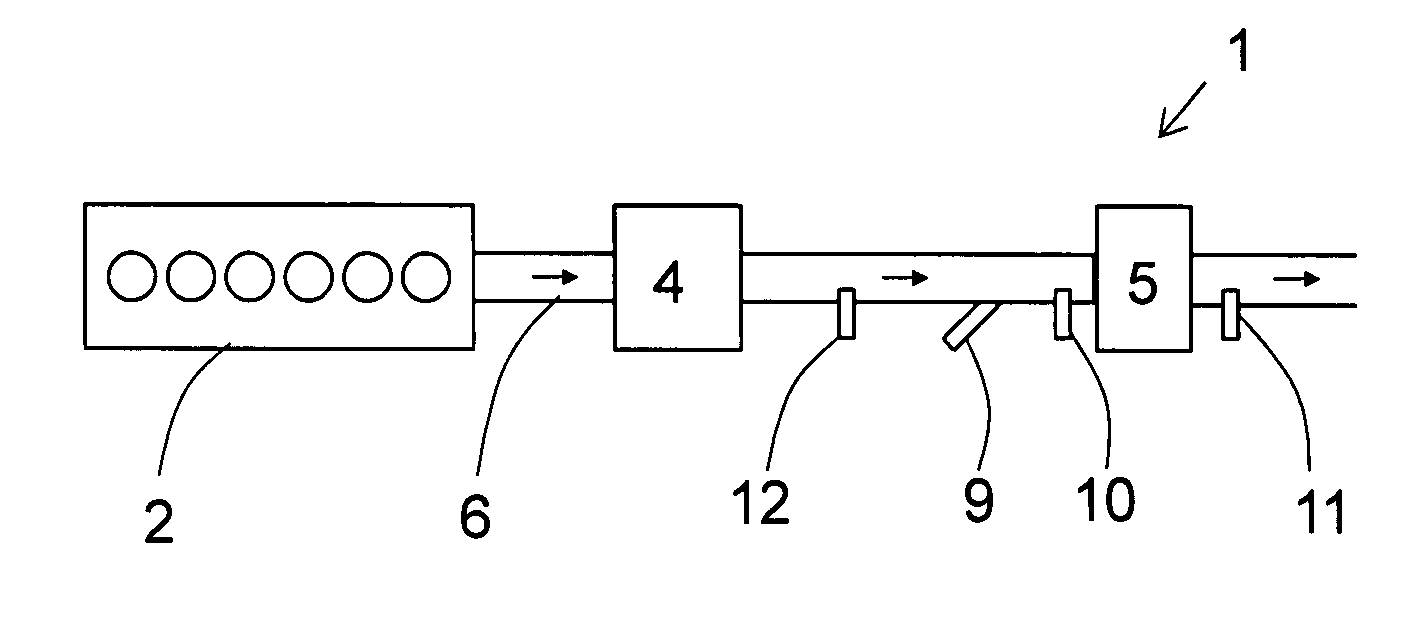
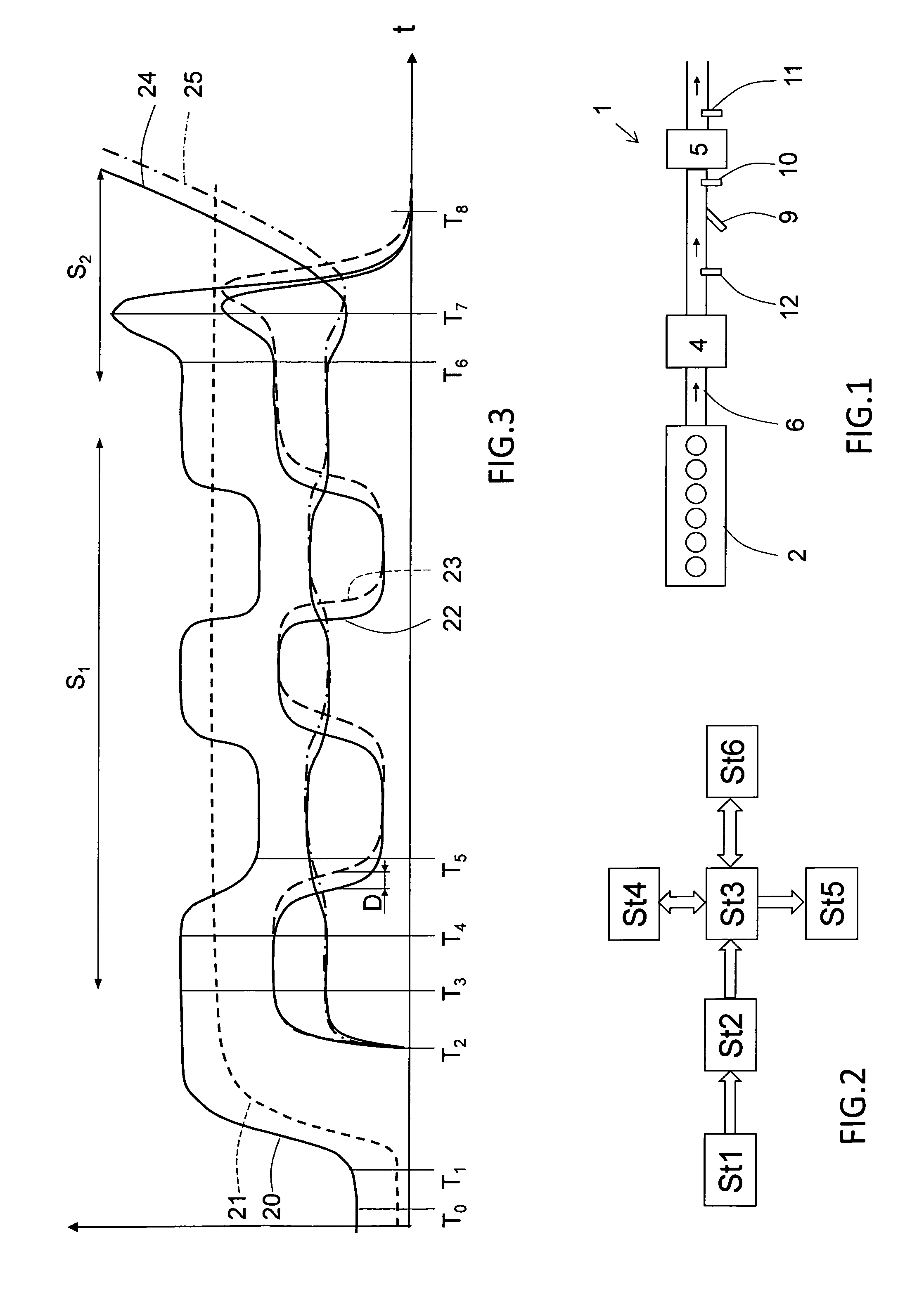
[0060]FIG. 1 shows schematically an exemplary layout of an exhaust aftertreatment system 1 of a diesel engine 2, in particular for a heavy truck or bus, or the like. The specific exhaust aftertreatment system 1 shown includes a particulate filter 4 to reduce the level of particulate matter. NOx emission from the engine 2 must also be reduced to comply with regulatory emission standards, and a SCR catalyst 5 is installed along the exhaust gas pipe 6 for this reason. Selective catalytic reduction is a means of converting NOx with the aid of a catalyst into nitrogen (N2) and water (H2O). A reductant, typically urea, is added to the e...


PUM


Abstract

A self-diagnosing method for diagnosing a selective catalytic reduction (SCR) system of a vehicle that includes an internal combustion engine. An SCR system is arranged downstream of the engine, and the SCR system includes at least one exhaust gas sensor that is sensitive to nitrogen oxides (NOx) gas. The method includes a first diagnosing sequence (S1) of ensuring that the vehicle is in a stationary state, controlling the engine to operate in a high NOx output engine operating state and in a low NOx output engine operating state, registering an output signal of the at least one exhaust gas sensor when the engine operates in each of the high NOx output engine operating state and low NOx output engine operating state, and diagnosing NOx measurement performance of the at least one exhaust gas sensor on the basis of the registered sensor output.

Description

BACKGROUND AND SUMMARY[0001]This invention relates to a self-diagnosing method for diagnosing a selective catalytic reduction (SCR) system of a vehicle, which comprises an internal combustion engine, wherein said SCR system is arranged downstream of the engine, wherein the SCR system comprises at least one exhaust gas sensor being sensitive to nitrogen oxides (NOx) gas.[0002]The invention also relates to a computer program comprising program code means for performing the inventive method, a computer program product comprising program code means stored on a computer readable medium for performing the inventive method, and a computer system for implementing, the inventive method.[0003]The method of the invention is particularly applicable for diagnosing a SCR system of large compression ignition engine that is configured to be powered with diesel or similar fuel types. Such an engine is frequently used in for example heavy duty trucks, buses, wheel loaders, articulated haulers, marine...

Claims


Application Information

Patent Timeline
Patent Type & Authority Applications(United States)
IPC IPC(8): F02D41/02F01N3/20F01N11/00
CPCF02D41/0235F01N11/00F01N2560/00F01N2900/04F01N3/2066F01N11/007F01N2430/08F01N2550/02F01N2560/026F01N2900/1402F01N2900/1622Y02A50/20Y02T10/12Y02T10/40
Inventor NILSSON, HENRIK
Owner VOLVO LASTVAGNAR AB
Why Eureka
Try Eureka