Permanent Magnet Rotating Electrical Machine and a Motor Vehicle Using Same

Active Publication Date: 2015-04-30
HITACHI ASTEMO LTD
View PDF1 Cites 20 Cited by
  • Summary
  • Abstract
  • Description
  • Claims
  • Application Information

AI Technical Summary

Benefits of technology

The present invention provides a permanent magnet rotating electrical machine that can increase the magnetic flux amount in a limited cross-section of the rotor core, improving performance and reducing fuel consumption in motor vehicles. This results in improved torque and power output while downsizing the machine.

Problems solved by technology

Heavy use of the reluctance torque leads to increase in inductance in a machine, which deteriorates the power factor and increases an inverter capacity and a battery capacity, resulting in an increase in weights of the components other than the rotating electrical machine.
Accordingly, the fuel consumption and the environmental loads may disadvantageously increase.

Method used


Image

  • Permanent Magnet Rotating Electrical Machine and a Motor Vehicle Using Same
  • Permanent Magnet Rotating Electrical Machine and a Motor Vehicle Using Same
  • Permanent Magnet Rotating Electrical Machine and a Motor Vehicle Using Same

Examples


embodiment 1

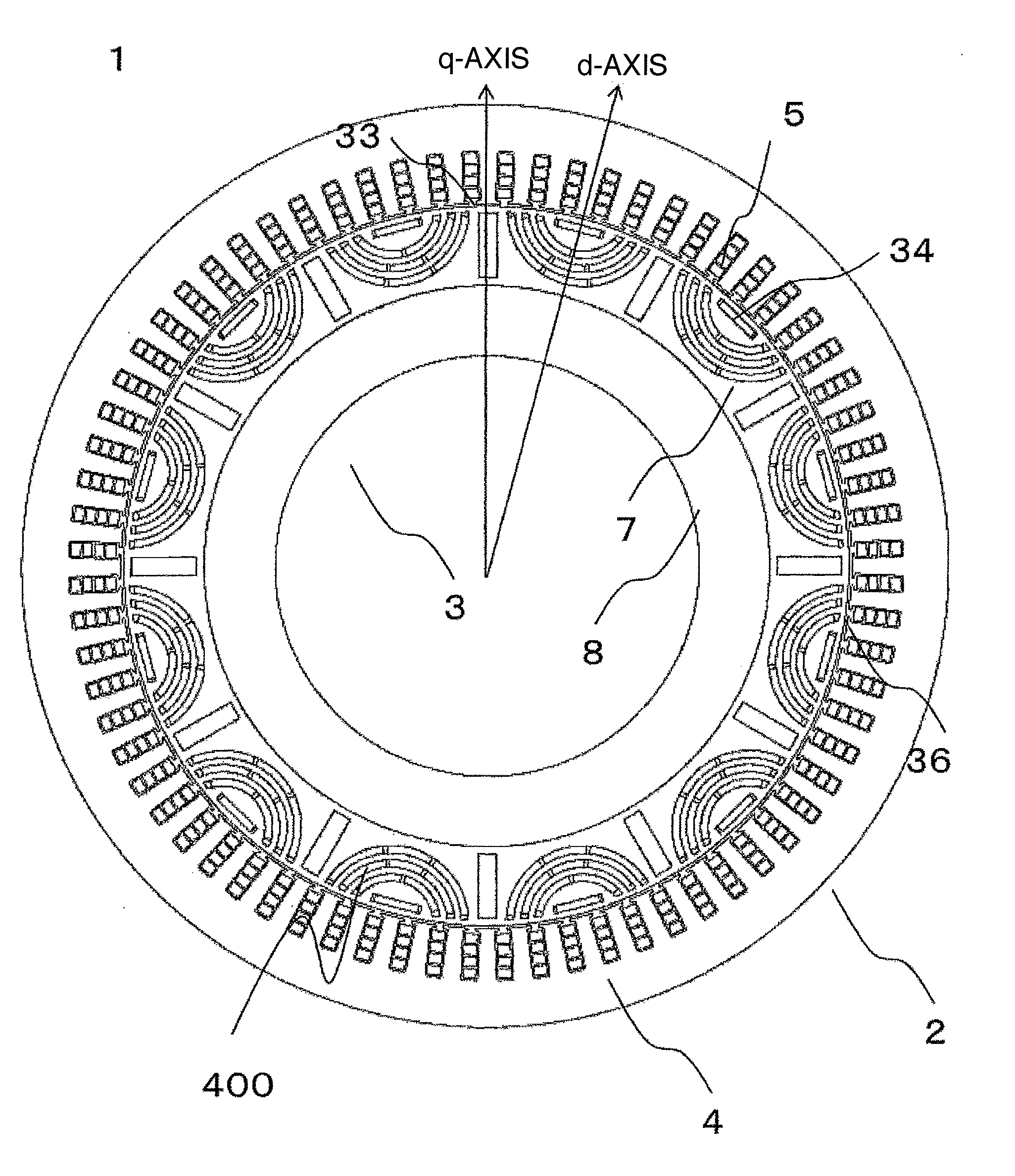
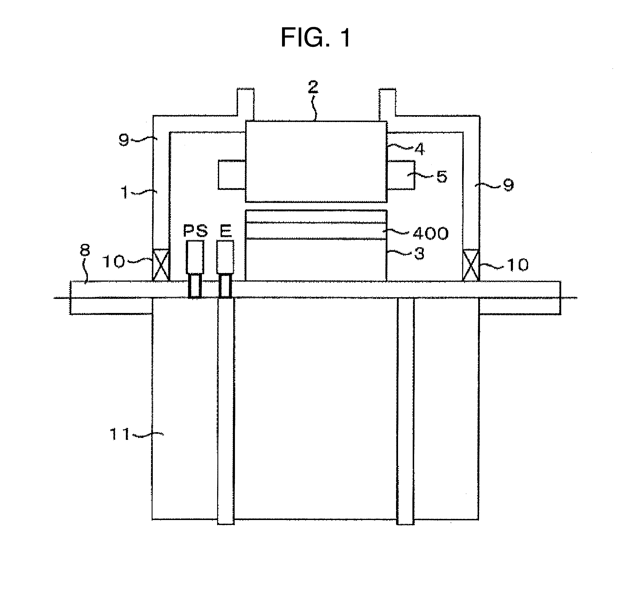
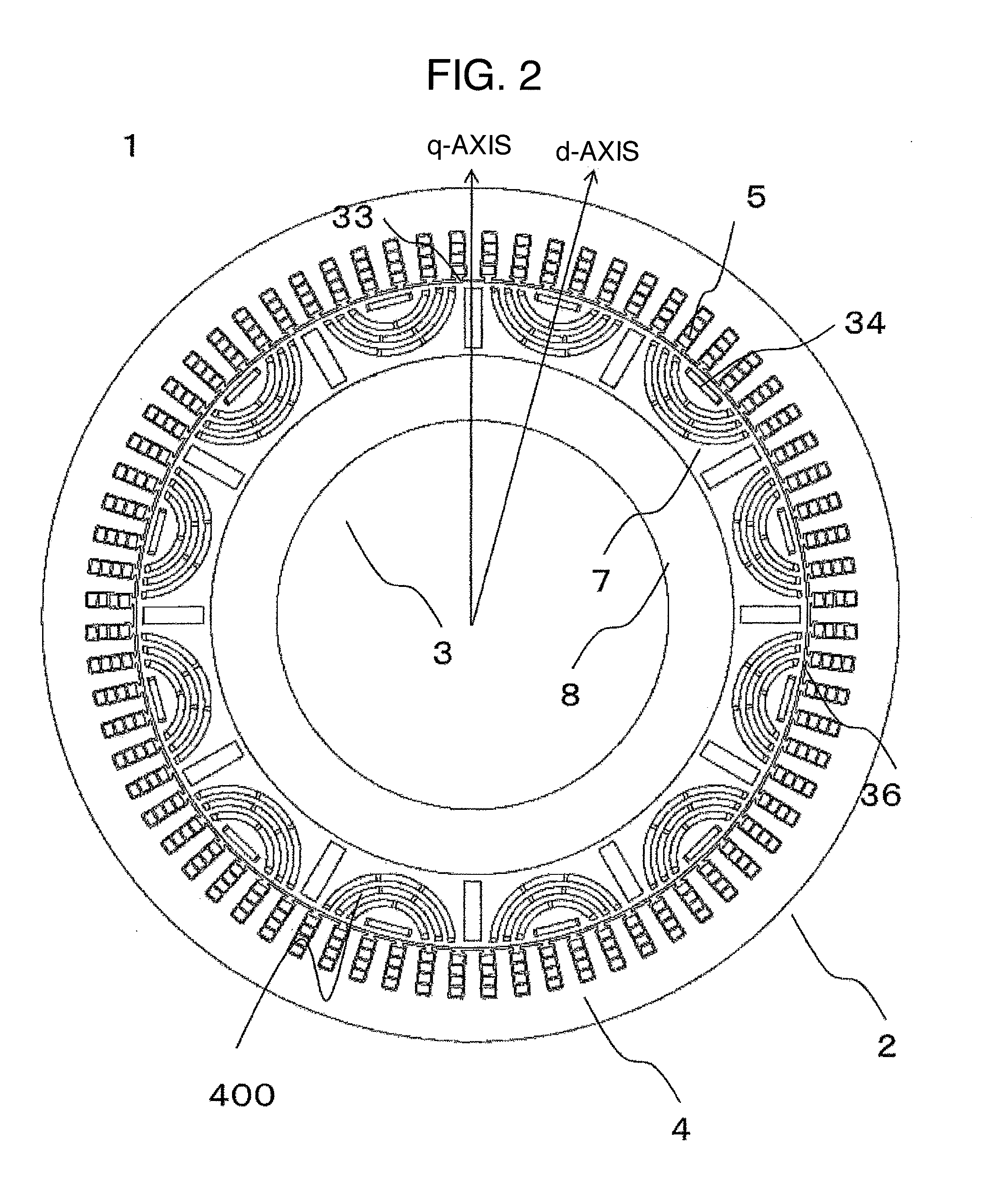
[0030]Embodiment 1 of the present invention will be described with reference to FIGS. 1 to 4. FIG. 1 is a partial cross-sectional view of a rotating electrical machine 1 using permanent magnets according to the embodiment of the present invention. A stator 2, which is included in the rotating electrical machine 1 using the permanent magnets, includes a stator core 4 and three-phase or multiphase stator windings 5 wound around slots formed in the stator core 4. The stator 2 is housed and held in a housing 11. A rotor 3 includes a rotor core 7 provided with magnet insertion holes 6 into which permanent magnets are inserted, permanent magnets 400 inserted into the magnet insertion holes 6 formed in the rotor core 7 for forming magnetic poles of the rotor, and a shaft 8. The shaft 8 is rotatably held in end brackets 9, which are fixed at both ends of the housing 11, by bearings 10.

[0031]The rotating electrical machine 1 includes a magnetic pole position detector PS for detecting a magne...

embodiment 2

[0046]FIG. 5 and FIG. 6 illustrate an embodiment in which a fourth magnet 404 is inserted. In the embodiment, a bathtub structure is applied to withstand high-speed rotation mechanically, and also, the fourth magnet 404 is inserted in order to increase magnetic flux further.

embodiment 3

[0047]FIG. 7 illustrates a rotor of an embodiment in which a large number of magnets as a flux barrier are laminated. It is a structure in which a bridge, which causes increase in Ld, is made thin. In the case of low-speed rotation, the problem of centrifugal force becomes less important, and thus, the shape in the present embodiment can be manufactured by two-color molding of a powder magnetic core and a magnet.


PUM


Abstract

A permanent magnet rotating electrical machine includes a rotor which has permanent magnets buried in a plurality of permanent magnet insertion slots that are provided in a rotor core, and the rotor is rotatably supported by a rotary shaft with a gap on the inner peripheral side of a stator. When the axis of magnetic flux for the permanent magnet is set as a d-axis and the position deviated from the d-axis by electrical angle of 90° is set as a q-axis, the permanent magnet insertion slot is located on the q-axis and a first permanent magnet magnetized in the direction orthogonal to the q-axis is buried in the permanent magnet insertion slot. The permanent magnet insertion slot is located on the d-axis and a second permanent magnet magnetized in the direction parallel to the d-axis is buried in the permanent magnet insertion slot, while at least one or more third permanent magnets buried in the permanent magnet insertion slots are provided between the first permanent magnet and the second permanent magnet. Thereby, the environmental load discharged from a motor vehicle is reduced.

Description

TECHNICAL FIELD[0001]The present invention relates to a permanent magnet rotating electrical machine and a motor vehicle using the same.BACKGROUND ART[0002]A rotating electrical machine for a vehicle, e.g., a drive motor for a hybrid electric vehicle, needs acceleration performance such as start performance and passing performance, and instantaneous acceleration torque is, therefore, required of the motor.[0003]In a case of a rotating electrical machine used for automobile application, a permanent magnet rotating electrical machine is used as a motor order to generate this instantaneous acceleration torque, and the generation of instantaneous, highly responsive torque is achieved by carrying a high current. The use of the high current described above, however, entails a problem of the loss of circuits in switching elements and bus bars of an inverter, resulting in an increase in the volume of the inverter for the need to take measures against generation of heat.[0004]Owing to this, ...

Claims


Application Information

Patent Timeline
IPC IPC(8): H02K1/27B60L11/18
CPCB60L11/1803H02K1/2773B60L50/51H02K1/2766H02K21/14Y02T10/64Y02T10/70
Inventor KOKA, HIDETOSHIKIKUCHI, SATOSHIMATSUNOBU, YUTAKASAITO, YASUYUKIHAMAHATA, SADAHIRO
Owner HITACHI ASTEMO LTD
Why Eureka
Try Eureka