Systems and methods for transcatheter treatment of valve regurgitation

a technology of valve regurgitation and transcatheter, which is applied in the field of systems and methods for transcatheter treatment of valve regurgitation, can solve the problems of significant number of patients who may not take medications regularly, medication can suffer from lack of patient compliance, and pharmacological therapies of mitral valve regurgitation may be inconvenien

Active Publication Date: 2015-04-30
POLARES MEDICAL INC
View PDF5 Cites 161 Cited by
  • Summary
  • Abstract
  • Description
  • Claims
  • Application Information

AI Technical Summary

Benefits of technology

[0016]The invention generally provides improved medical devices, systems, and methods. In some embodiments, the invention provides new implants, implant systems, and methods for treatment of mitral valve regurgitation and other valve diseases. In some embodiments, the implants comprise a coaptation assist body which remains within the blood flow path as the valve moves back and forth between an open-valve configuration and a closed valve configuration. The coaptation assist body may extend laterally across some, most, or all of the width of the valve opening, allowing coaptation between at least one of the native leaflets and the implant body. In some embodiments, also disclosed is an implant, which can be a cardiac implant, such as a coaptation assist body, cardiac patch, replacement heart valve, annuloplasty ring, pacemaker, sensor, or other device. At least one ribbon (e.g., clip) can be configured to extend from the implant body. The ribbon can be made of a shape memory material having a preformed shape with at least one curve. The ribbon can be movable from a first compressed configuration to a second expanded configuration. The ribbon can be configured to provide a force, such as a compressive force to clip to a body structure, such as an intracardiac structure. In some embodiments, the intracardiac structure is a single native valve leaflet, and the force is applied between a first surface of the ribbon and a second surface of the ribbon opposed from the first surface of the ribbon. The compressive force can be sufficient to secure the implant in the vicinity of the native valve annulus.

Problems solved by technology

A variety of therapies have been applied for treatment of mitral valve regurgitation, and still other therapies may have been proposed but not yet actually used to treat patients.
However, medications can suffer from lack of patient compliance.
A significant number of patients may occasionally (or even regularly) fail to take medications, despite the potential seriousness of chronic and / or progressively deteriorating mitral valve regurgitation.
Pharmacological therapies of mitral valve regurgitation may also be inconvenient, are often ineffective (especially as the condition worsens), and can be associated with significant side effects (such as low blood pressure).
Regardless, open mitral valve surgery is generally a very invasive treatment carried out with the patient under general anesthesia while on a heart-lung machine and with the chest cut open.
Complications can be common, and in light of the morbidity (and potentially mortality) of open-heart surgery, the timing becomes a challenge—sicker patients may be in greater need of the surgery, but less able to withstand the surgery.
Procedures that are done with robots or through endoscopes are often still quite invasive, and can also be time consuming, expensive, and in at least some cases, quite dependent on the surgeon's skill.
While these various approaches and tools have met with differing levels of acceptance, none has yet gained widespread recognition as an ideal therapy for most or all patients suffering from mitral valve regurgitation.
Unfortunately, sealing between the native leaflets and the full perimeter of a balloon or other coaxial body may prove challenging, while the significant contraction around the native valve annulus during each heart beat may result in significant fatigue failure issues during long-term implantation if a buttress or anchor interconnecting cross member is allowed to flex.
Moreover, the significant movement of the tissues of the valve may make accurate positioning of the implant challenging regardless of whether the implant is rigid or flexible.

Method used


Image

  • Systems and methods for transcatheter treatment of valve regurgitation
  • Systems and methods for transcatheter treatment of valve regurgitation
  • Systems and methods for transcatheter treatment of valve regurgitation

Examples


Embodiment Construction

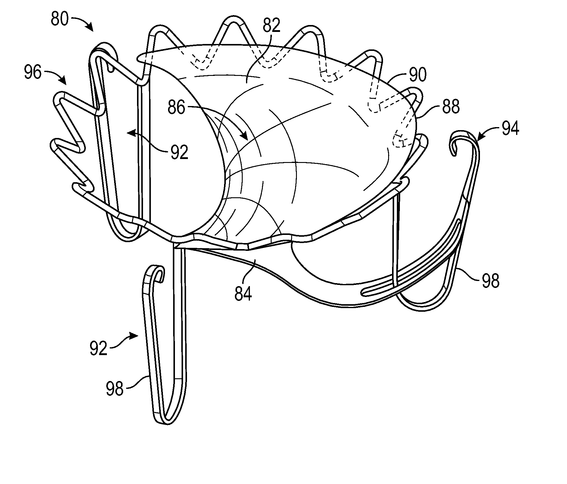
[0039]Disclosed herein are improved medical devices, systems, and methods, often for treatment of mitral valve regurgitation and other valve diseases including tricuspid regurgitation. While the description that follows includes reference to the anterior leaflet in a valve with two leaflets such as the mitral valve, it is understand that “anterior leaflet” could refer to one or more leaflets in a valve with multiple leaflets. For example, the aortic valve or tricuspid valve typically has 3 leaflets so the “anterior” could refer to one or two of the medial, lateral, and posterior leaflets. The implants described herein will generally include a coaptation assist body (sometimes referred to herein as a valve body) which is generally along the blood flow path as the leaflets of the valve move back and forth between an open-valve configuration (with the anterior leaflet separated from valve body) and a closed-valve configuration (with the anterior leaflet engaging opposed surfaces of the...


PUM


Abstract

The invention relates to a device for use in the transcatheter treatment of mitral valve regurgitation, specifically a coaptation assistance devices for implantation across the valve; a system including the coaptation enhancement element and anchors for implantation; a system including the coaptation enhancement element, and one or more of the following: transseptal sheath, anchor delivery catheter, implant delivery catheter, and clip delivery catheter; and methods for transcatheter implantation of a coaptation element across a heart valve.

Description

BACKGROUND OF THE INVENTION[0001]1. Field of the Invention[0002]The present invention generally provides improved medical devices, systems, and methods, typically for treatment of heart valve disease and / or for altering characteristics of one or more valves of the body. Embodiments of the invention include implants for treatment of mitral valve regurgitation.[0003]The human heart receives blood from the organs and tissues via the veins, pumps that blood through the lungs where the blood becomes enriched with oxygen, and propels the oxygenated blood out of the heart to the arteries so that the organ systems of the body can extract the oxygen for proper function. Deoxygenated blood flows back to the heart where it is once again pumped to the lungs.[0004]The heart includes four chambers: the right atrium (RA), the right ventricle (RV), the left atrium (LA) and the left ventricle (LV). The pumping action of the left and right sides of the heart occurs generally in synchrony during the o...

Claims


Application Information

Patent Timeline
Patent Type & Authority Applications(United States)
IPC IPC(8): A61F2/24
CPCA61F2/2442A61F2/2466A61F2/2454A61B17/0401A61F2/2463A61B2017/00243A61B2017/0414A61B2017/0441A61B2017/0649A61F2/2412A61F2210/0014A61F2220/0008
Inventor KHAIRKHAHAN, ALEXANDER K.LESH, MICHAEL D.KLENK, ALAN R.
Owner POLARES MEDICAL INC
Why Eureka
Try Eureka