Mass spectrometer with laser spot pattern for maldi

a mass spectrometer and laser spot pattern technology, which is applied in the direction of instruments, particle separator tube details, separation processes, etc., can solve the problems of too few ions per shot from this small sample volume, excessive consumption of sample in undesirable way, and very soon reach the level of spontaneous fragmentation of ionized molecules, etc., to achieve an exceptional high degree of ionization of analyte ions

Active Publication Date: 2015-05-07
BRUKER DALTONIK GMBH & CO KG
View PDF4 Cites 25 Cited by
  • Summary
  • Abstract
  • Description
  • Claims
  • Application Information

AI Technical Summary

Benefits of technology

[0014]Around the pattern (i.e., around the central laser spots with almost homogeneous intensity), further intensity peaks can occur, but their amplitude is at least a factor of three lower. If they interfere, they can be filtered out with the aid of apertures. More than 60% of the total energy of the laser beam is contained in the several prominent, central intensity peaks of the pattern. The spot pattern with intensity peaks of the same height produces an outstandingly high degree of ionization for analyte ions.

Problems solved by technology

This means, however, that energy densities very soon reach levels at which spontaneous fragmentation of the ionized molecules occurs.
On the other hand, if one remains below this limit, too few ions are generated per shot from this small sample volume.
With the fine spot pattern, hardly any sample material is spattered, something that is always a problem for larger spot diameters with larger amounts of molten material.
The other spots of the pattern would then produce hardly any analyte ions in comparison, but would consume sample in an undesirable way.
Another possibility is to use diffractive beam splitters, but their production costs are high.
Since fused silica has to be used for the optical elements at these wavelengths, it is usually very expensive to manufacture appropriate beam-shaping optical devices.
The components for equipment in accordance with these documents are relatively expensive, however, and the components used must be adjusted very precisely and reproducibly.

Method used


Image

  • Mass spectrometer with laser spot pattern for maldi
  • Mass spectrometer with laser spot pattern for maldi
  • Mass spectrometer with laser spot pattern for maldi

Examples


Embodiment Construction

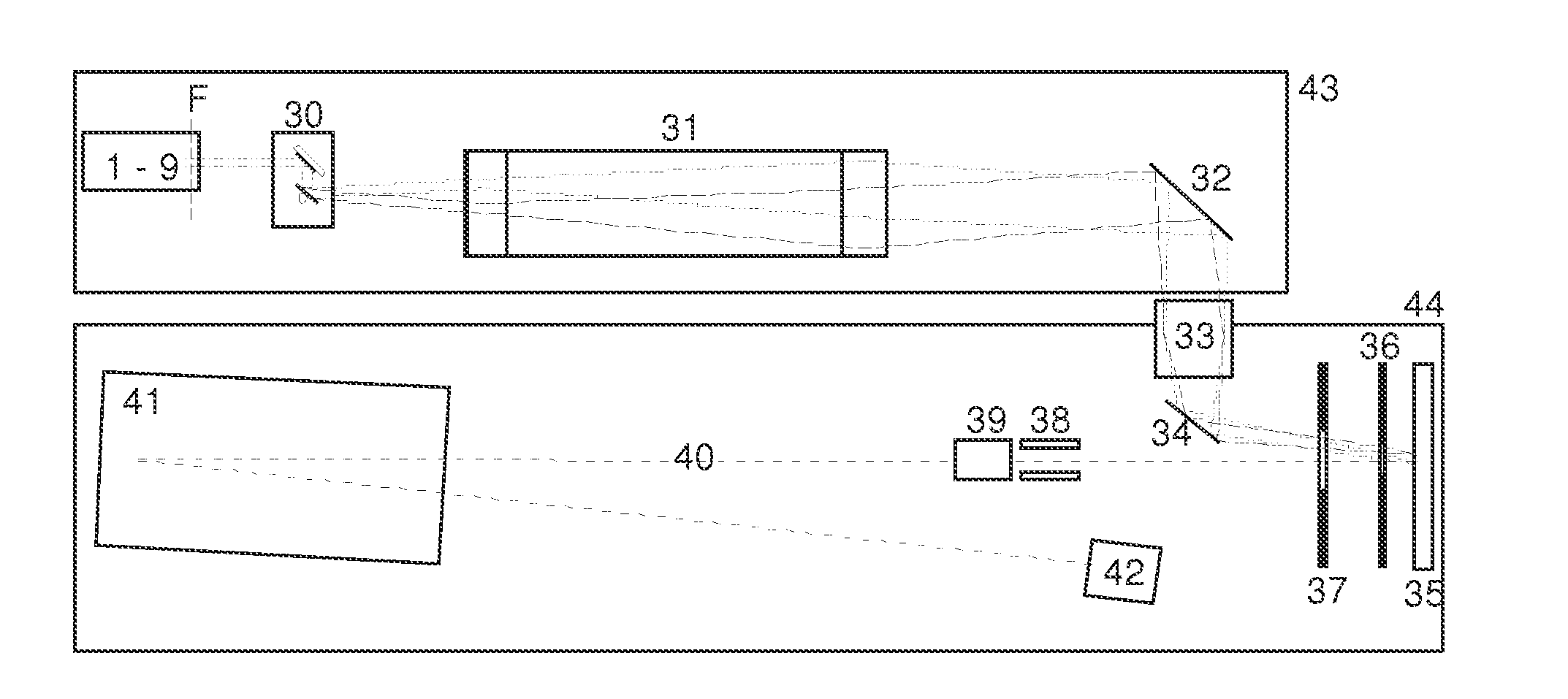
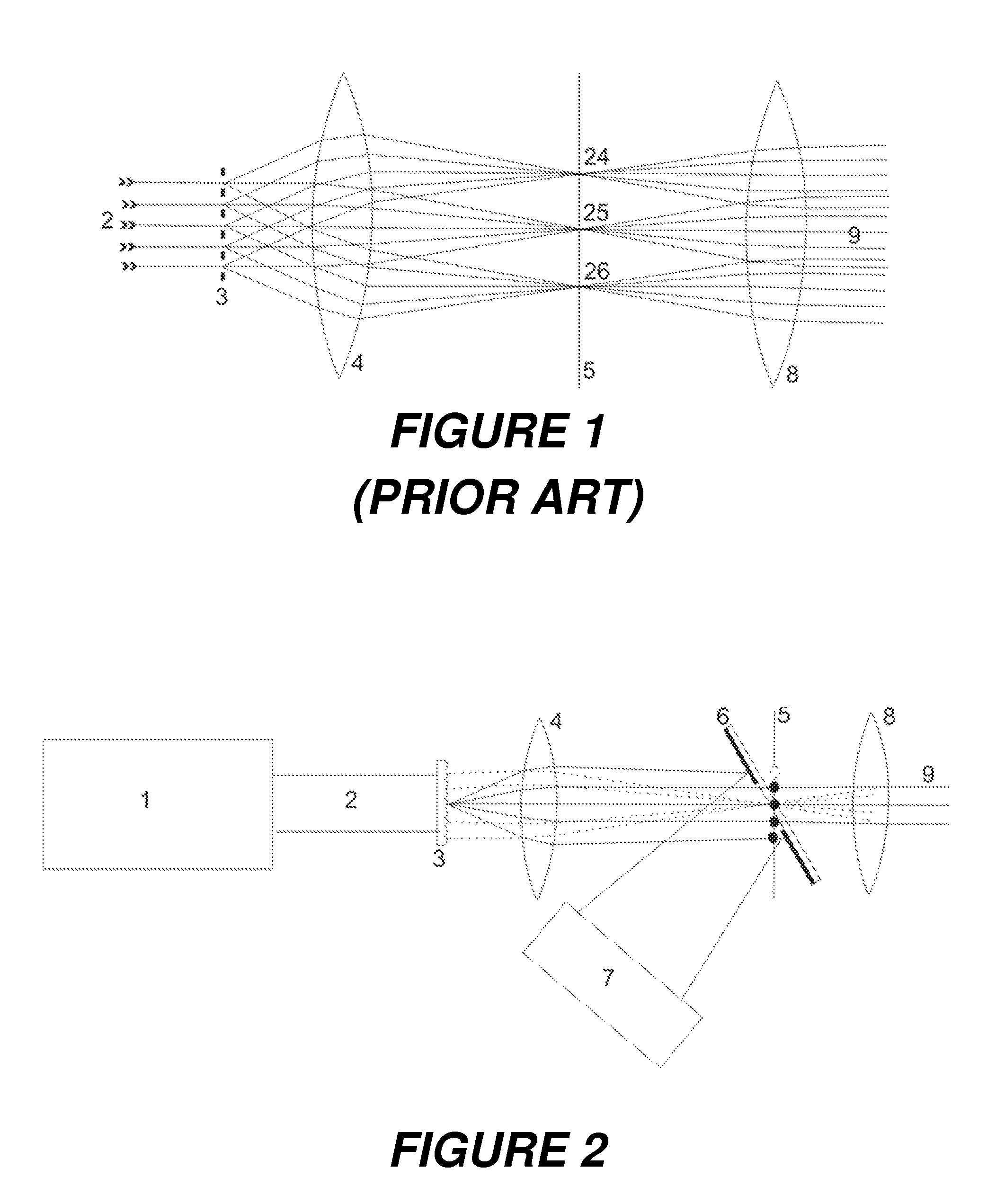
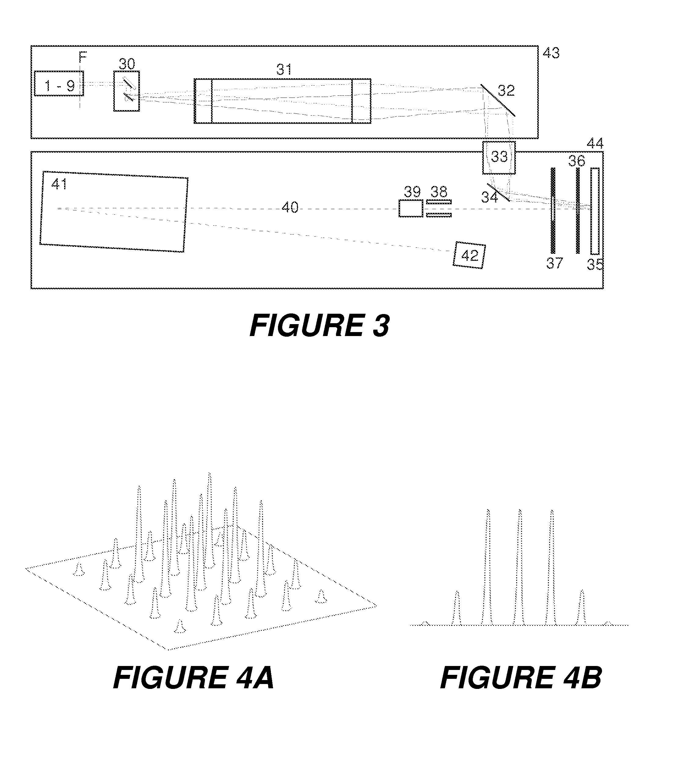
[0024]The invention proposes a mass spectrometer with a laser system whose main objective is to generate spatially divided spot patterns with several peaks of approximately equally high intensity on the MALDI sample with only small energy losses, where the pattern-generating elements are inexpensive and not sensitive to adjustment. In a first embodiment, which will be described further below, nine spots are generated in each case; and five spots with a second embodiment; but other patterns with other numbers of spots also seem to be possible. The diameters of the spots can be changed as desired by shifting lenses, for example. Single spots or spot patterns with more than twenty spots can also be produced, which means that an optimum degree of ionization for analyte ions can be achieved for any sample shape, any type of preparation, and any analytical ask.

[0025]In other words, a mass spectrometer with a UV laser system is proposed which, with very low energy losses, produces not only...


PUM


Abstract

The invention relates to mass spectrometers with an ion source, comprising a UV laser system for mass spectrometric analyses with ionization of analyte molecules in a sample by matrix-assisted laser desorption, which, with very low energy losses, can produce a spatially distributed spot pattern with several intensity peaks of equal height, thus making it possible to achieve an optimum degree of ionization of analyte ions for any task. Such a spot pattern can be generated from the UV beam with high transverse coherence, using a combination of a lens array and a lens, provided that the lens array satisfies a mathematical condition for separation of the micro-lenses from each other (pitch) and their focal length. For example, a lens array with square or round lenses produces a pattern of nine and five spots, respectively. The lens arrays are inexpensive and do not require any lateral adjustment in this arrangement.

Description

BACKGROUND OF THE INVENTION[0001]1. Field of the Invention[0002]The invention relates to a mass spectrometer with a laser desorption ion source, comprising a laser system for mass spectrometric analyses with ionization of the analyte molecules of a sample by matrix-assisted laser desorption.[0003]2. Description of the Related Art[0004]Over the past twenty years, two methods have gained acceptance in the mass spectrometry of biological macromolecules: matrix-assisted laser desorption and ionization (MALDI) and electrospray ionization (ESI). The biological macromolecules to be analyzed are termed analyte molecules below. In the MALDI method, the analyte molecules are generally prepared on the surface of a sample support in a solid, polycrystalline matrix layer, and are predominantly ionized with a single charge, whereas in the ESI method they are dissolved in a liquid and ionized with multiple charges. It was these two methods which made possible the mass spectrometric analysis of bio...

Claims


Application Information

Patent Timeline
Patent Type & Authority Applications(United States)
IPC IPC(8): H01J49/16H01J49/00H01J49/26
CPCH01J49/164H01J49/0004H01J49/26G02B3/0006H01S3/005
Inventor HAASE, ANDREAS
Owner BRUKER DALTONIK GMBH & CO KG
Why Eureka
Try Eureka