Vehicle heating apparatus and system and method of doing the same
- Summary
- Abstract
- Description
- Claims
- Application Information
AI Technical Summary
Benefits of technology
Problems solved by technology
Method used
Image
Examples
second embodiment
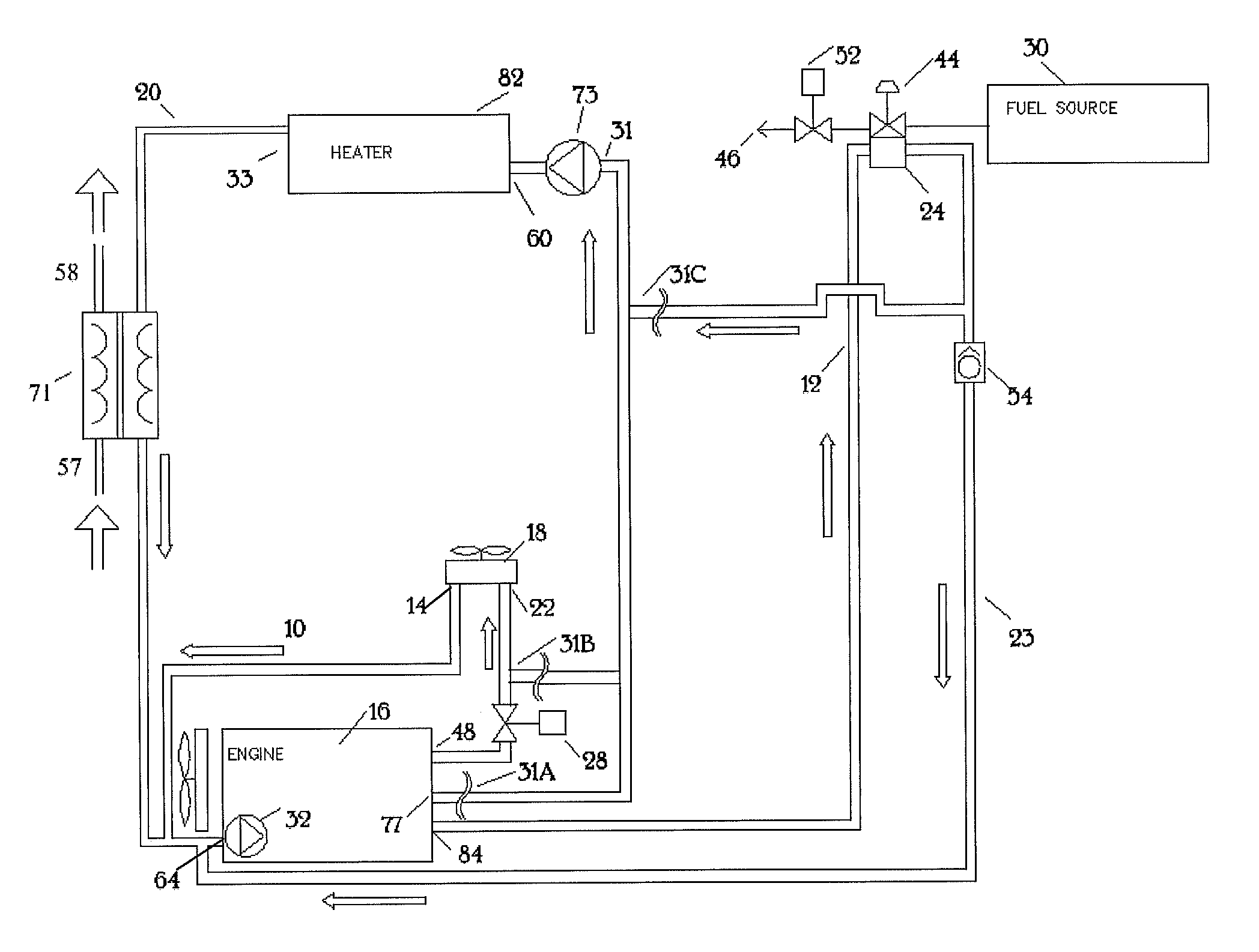
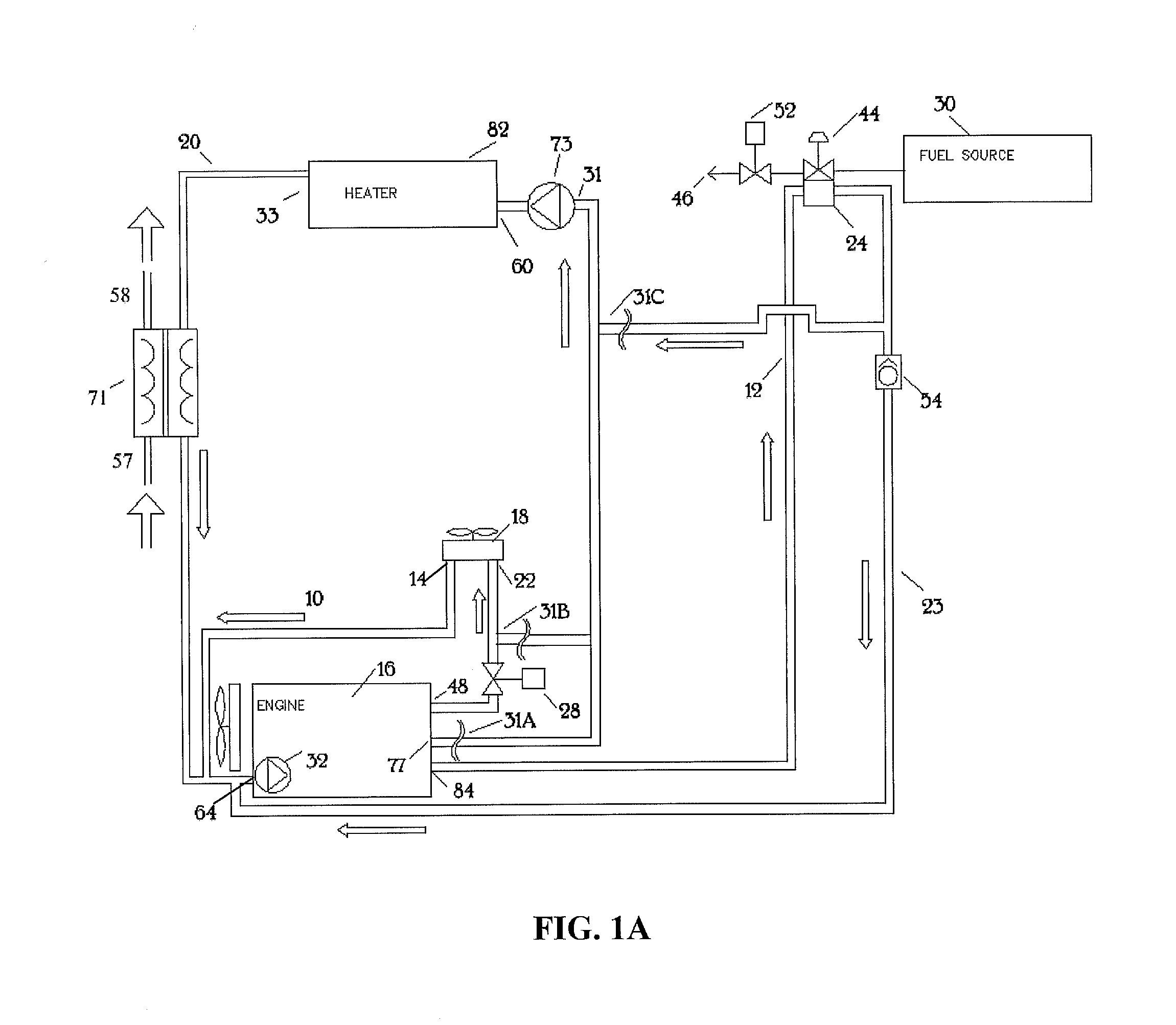
[0284]FIG. 2 is a flow diagram showing the vehicle engine's cooling system, which includes a coolant reservoir or fluid tank 43, which may also be called a water jacket. The engine's cooling system may comprise an optional heater 82 with a fuel-operated heat exchanger in a coolant reservoir 43. The coolant reservoir 43 may be insulated (not shown) in some embodiments to increase the efficiency of the heater system. The additional coolant reservoir 43 provides heat to the various fluid circuits and systems such that the fluid circuits may be heated together or heated in isolation from one another. In another embodiment, the heater 82 is outfitted with a larger heat exchanger 59, which is also referred to as a heat exchanger tank or a tank. The heat exchanger tank 59 may be a cylindrical shape or any other shape, such as square or rectangular. This embodiment provides isolation from direct contact to the existing vehicle systems. Further, the heater 82 may further be constructed to fa...
third embodiment
[0302]FIG. 7C is a front elevation view of a supplemental heater and FIG. 7D is a perspective view of section D-D of the supplemental heater of FIG. 7C. The numbering used in FIG. 7D correlates to the numbering used in FIGS. 6B and 7B. However, the embodiment shown in FIG. 7D is slightly different from the embodiment shown in FIG. 7B. For example, the refractory 95 in FIG. 7D is thicker / wider than the refractory in FIG. 7B. The larger refractory 95 of FIG. 7D removes more gas from behind the igniter 79 tip than the smaller refractory 95 of FIG. 7B. This makes the area behind the ignition source 79 flatter and the pressure and gas flow at the ignition source 79 tip more stable than the thinner refractory 95. In one embodiment, the combustion chamber 101 has a volume of between about 240 and 280 cubic inches. In a preferred embodiment, the combustion chamber 101 has a volume of between about 255 and 265 cubic inches. In a more preferred embodiment, the combustion chamber 101 has a vol...
fourth embodiment
[0306]FIG. 11 is a front right perspective view of a supplemental heater 82. The heater 82 and heater system may include a coolant reservoir 43 to provide a medium for one or more coolant paths and devices to be heated. The coolant reservoir 43 has an end piece 93, a coolant outlet port 33 where coolant heated by the combustion chamber (not shown) exits the heater 82, and a coolant inlet port 60 where coolant to be heated enters the heater 82. In some embodiments, the inlet port 60 is located on the bottom or lower side of the coolant reservoir 43 and the outlet port 33 is located on the top or upper side of the coolant reservoir 43 because heated coolant rises and because gas or air bubbles rise and move the liquid with bubbles. The heater also has a control thermostat 124 on the water jacket 43 to measure the temperature of the water jacket 43 or the fluid within the water jacket 43. In some embodiments, the coolant reservoir 43 may be encased or encircled in insulation to increas...
PUM
 Abstract
Description
Claims
Application Information
 - R&D
- Intellectual Property
- Life Sciences
- Materials
- Tech Scout
- Unparalleled Data Quality
- Higher Quality Content
- 60% Fewer Hallucinations
Browse by: Latest US Patents, China's latest patents, Technical Efficacy Thesaurus, Application Domain, Technology Topic, Popular Technical Reports.
© 2025 PatSnap. All rights reserved.Legal|Privacy policy|Modern Slavery Act Transparency Statement|Sitemap|About US| Contact US: help@patsnap.com


