Plastics moulding composition and use thereof

Active Publication Date: 2015-06-25
EMS PATENT AG
View PDF4 Cites 26 Cited by
  • Summary
  • Abstract
  • Description
  • Claims
  • Application Information

AI Technical Summary

Problems solved by technology

The integration of electrical and mechanical functions in an i

Method used


Image

  • Plastics moulding composition and use thereof

Examples


examples b1 to b17

AND COMPARATIVE EXAMPLES VB1 TO VB6

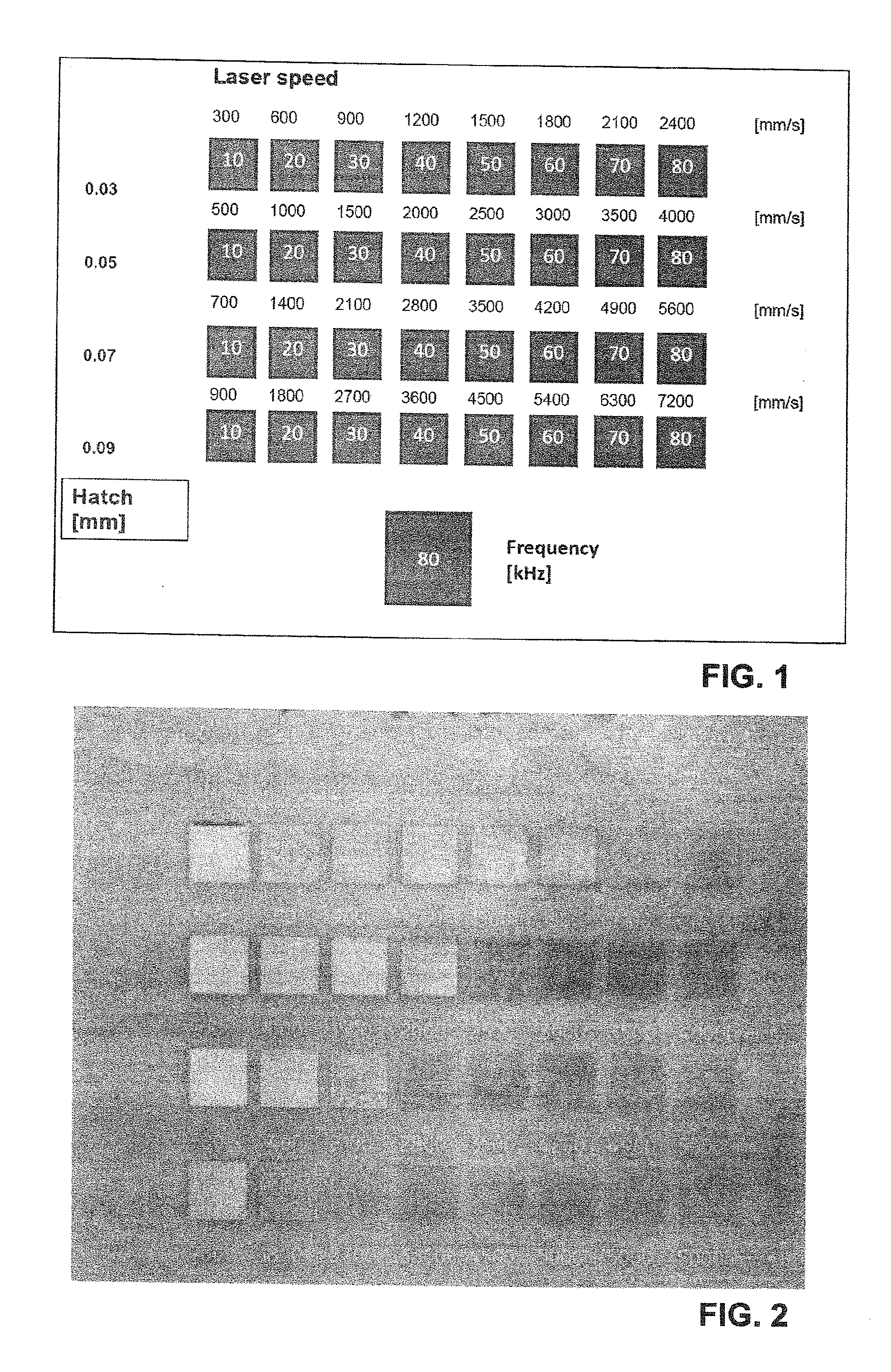
[0142]The components specified in Tables 2 and 3 are compounded in a twin-screw extruder from Werner and Pfleiderer having a screw diameter of 25 mm, with specified processing parameters (cf. Table 1). The polyamide pellets along with the additives are metered into the intake zone, while the glass fibre is metered into the polymer melt via a side feeder 3 barrel units ahead of the die. The compounds are taken off as extrudate from a nozzle 3 mm in diameter, and pelletized after water cooling. The pellets were dried at 110° C. under a reduced pressure of 30 mbar for 24 hours. The compounded formulations are injection-moulded on an Arburg Allrounder 320-210-750 machine to give sample bodies with defined cylinder temperatures for zones 1 to 4 and with a defined mould temperature (see Table 1).

TABLE 1Compounding and injection moulding conditionsfor the inventive and comparative examplesCompounding / processing parametersB1-B17, VB1-VB6CompoundingBarrel t...


PUM

PropertyMeasurementUnit
Lengthaaaaaaaaaa
Fractionaaaaaaaaaa
Fractionaaaaaaaaaa

Abstract

A description is given of thermoplastic, white-pigmented plastics moulding compositions having improved mechanical properties, especially for LDS applications. The thermoplastic moulding composition consists of:
    • (A) 20-88 wt % of a mixture consisting of
      • (A1) 60-100 wt % of a thermoplastic
      • (A2) 0-40 wt % of a mixture of
        • (A2_1) 0-40 wt % of a thermoplastic other than (A1);
        • (A2_2) 0-40 wt % of impact modifiers other than (A1) and (A2_1);
    • (B) 10-70 wt % of fibrous adjuvants;
    • (C) 0.1-10 wt % of an LDS additive or of a mixture of LDS additives, at least one LDS additive being selected from the following group: metal oxide based on copper, neodymium, molybdenum, bismuth, antimony or tin, with the proviso that spinels are excluded; metal phosphate; metal hydroxide phosphate;
    • (D) 0.1-20 wt % of white pigment;
    • (E) 0-20 wt % of particulate filler other than C and/or D;
    • (F) 0-2 wt % of further, different additives;
a the sum of (A)-(F) making up 100 wt %.

Description

TECHNICAL FIELD[0001]The present invention relates to thermoplastic moulding compositions having improved mechanical properties. Besides glass fibres, the moulding compositions comprise a white pigment and also an LDS additive. Mouldings produced therefrom can be subjected, following partial irradiation, to targeted metallization. The moulding compositions of the invention find use in particular for the production of injection-moulded circuit carriers.PRIOR ART[0002]Moulded Interconnect Devices (MIDs)—circuit carriers made from thermoplastics—have the advantage over existing circuit carriers of improved design freedom, of effective environmental compatibility, and of the rationalization potential relating to the process of producing the end product. The integration of electrical and mechanical functions in an injection moulding may lead to miniaturization of the assembly. Moreover, entirely new functions can be realized, and virtually any desired forms can be designed. 2-Component i...

Claims


Application Information

Patent Timeline
IPC IPC(8): C08L77/06H05K5/02C08L77/02
CPCC08L2205/03C08L2205/16C08L77/06C08L2205/025H05K5/0247C08L2203/20C08L77/02C08L2205/02C08K13/04C08K7/14C08K2003/3036C08K2003/2241C08K3/22C08K3/24C08K3/30C08K3/32C08K7/02C08L77/00Y10T428/1352
Inventor STOPPELMANN, GEORG
Owner EMS PATENT AG
Why Eureka
Try Eureka