Methods and compositions for separating or enriching blood cells

a technology of blood cells and compositions, applied in the field of bioseparation, can solve the problem of unnecessary centrifugation steps, and achieve the effect of minimizing the loss of nucleated cells

Inactive Publication Date: 2015-07-02
AVIVA BIOSCI
View PDF3 Cites 9 Cited by
  • Summary
  • Abstract
  • Description
  • Claims
  • Application Information

AI Technical Summary

Benefits of technology

[0012]In some aspects, the present invention recognizes that diagnosis, prognosis, and treatment of many conditions can depend on the enrichment of target cells and / or cellular organelles from a complex fluid sample. Often, enrichment can be accomplished by one or more separation steps using a filtration device with slots that filter the cells according to the size, shape, deformability, binding affinity and / or binding specificity of the cells. For example, nucleated cells may be separated from non-nucleated red blood cells in peripheral blood samples using the filtration device. In comparison to removal of red blood cells based on cell lysis techniques, the filtration device disclosed in the present application may deplete red blood cells based on their size, shape, deformability, binding affinity and / or binding specificity, and minimize loss of nucleated cells due to nonspecific lysis. Further, it may achieve minimal alteration to nucleated cell volume and make a centrifugation step unnecessary.
[0013]In particular, the separation of fetal cells from maternal blood samples can greatly aid in the detection of fetal abnormalities or a variety of genetic conditions. In some aspects, the present invention recognizes that the enrichment or separation of rare malignant cells from patient samples, such as the isolation of cancerous cells from patient body fluid samples, can aid in the detection and typing of such malignant cells and therefore aid in diagnosis and prognosis, as well as in the development of therapeutic modalities for patients.

Problems solved by technology

Further, it may achieve minimal alteration to nucleated cell volume and make a centrifugation step unnecessary.

Method used


Image

  • Methods and compositions for separating or enriching blood cells
  • Methods and compositions for separating or enriching blood cells
  • Methods and compositions for separating or enriching blood cells

Examples


example 1

Fabrication of a Filter for Removing Red Blood Cells from a Blood Sample

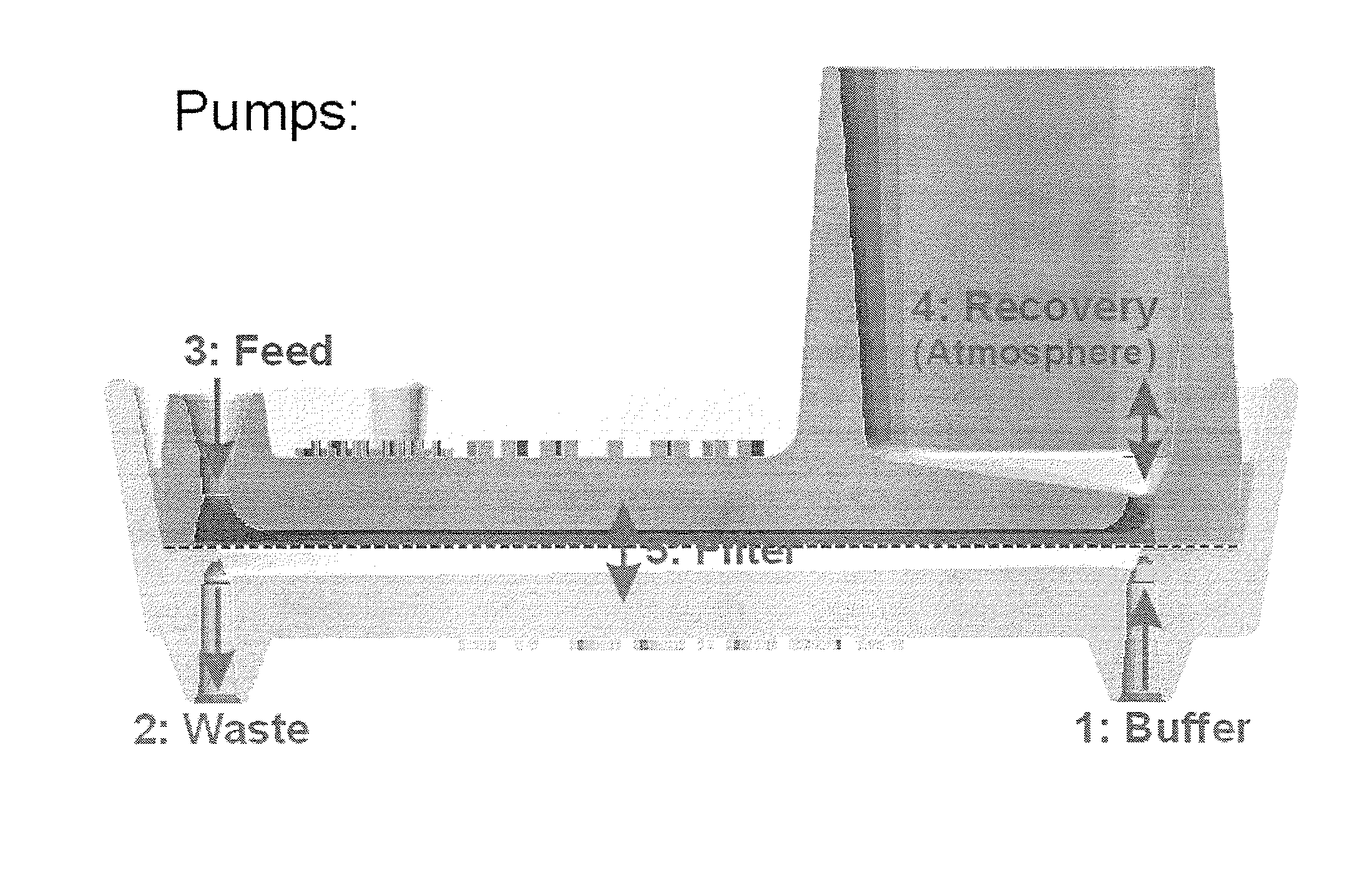
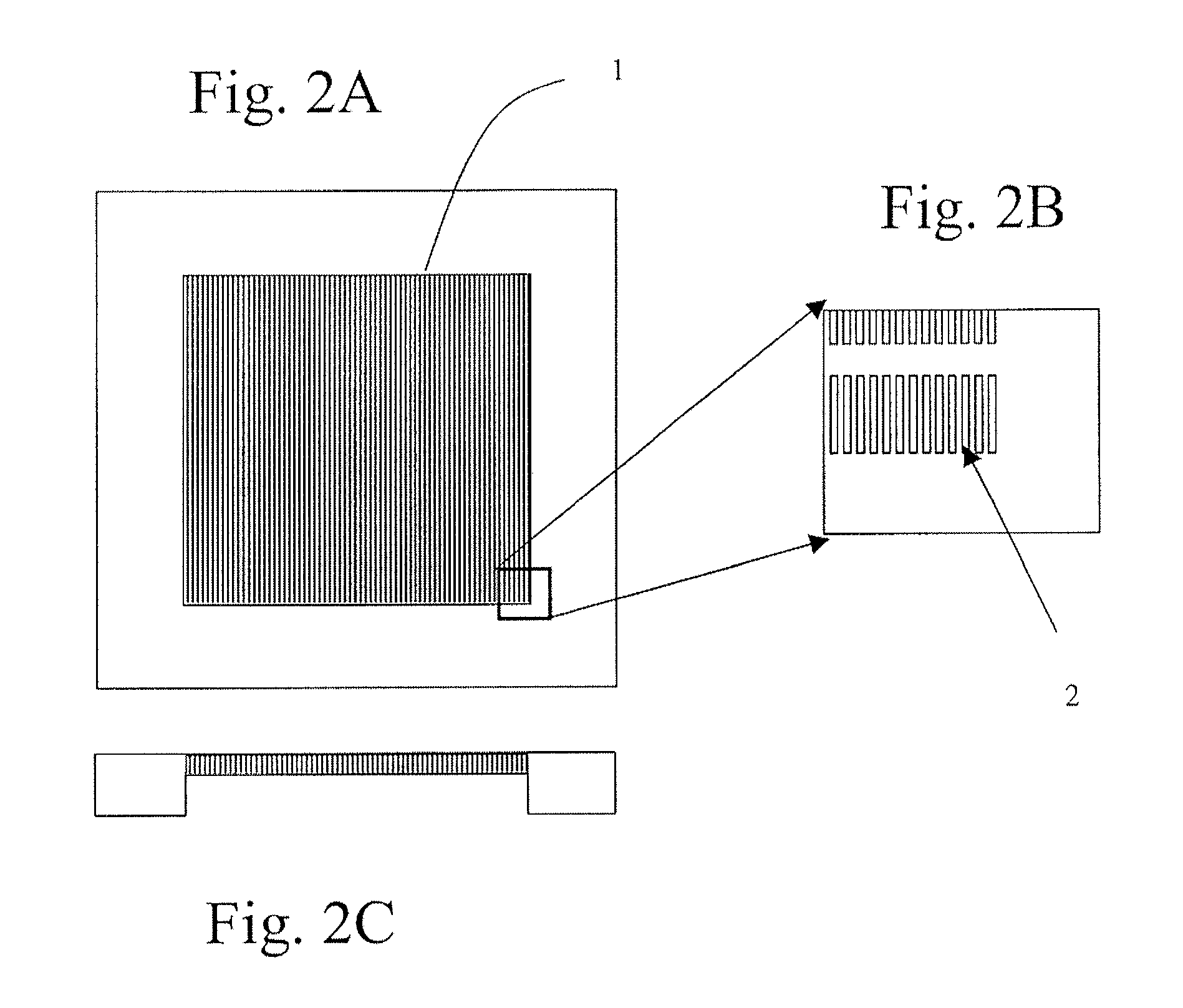
[0530]A silicon chip of dimensions (1.8 cm by 1.8 cm×500 micron) was used to fabricate a filtration area of 1 cm by 1 cm by 50 micron with slots having dimensions from about 0.1 micron to about 1000 microns, preferably from about 20 to 200 microns, preferably from about 1 to 10 microns, more preferably 2.5 to 5 microns. The slots were vertically straight with a maximum tapered-angle of less than 2%, preferably less than about 0.5% with an offset distance between neighboring columns of the filter slots were 1 to 500 microns, preferably from 5 to 30 microns.

[0531]Manufacturing included providing a silicon chip having the above referenced dimensions and coating the top and bottom of the silicon chip with a dielectric layer. A cavity along the bottom portion of the chip was then created. The cavity was formed by removing an appropriate cavity pattern from the dielectric layer, and then etching the silicon chip gener...

example 2

Chemical Treatment of a Microfabricated Filter

[0532]A filter chip made as described in Example 1 was placed on a ceramic heating plate in an oven and heated at 800 degrees Celsius for 2 hours in oxygen containing gas (e.g. air). The heating source was then turned off the chips are slowly cooled overnight. This results in a thermally grown layer on the surface of the chip.

[0533]A nitride layer could also be deposited onto the filter surface. An oxide layer is put on the surface of the chip by low-pressure chemical vapor deposition (LPCVD) in a reactor at temperatures up to ˜900° C. The deposited film is a product of a chemical reaction between the source gases supplied to the reactor. The process is typically performed on both sides of the substrate at the same time to form a layer of Si3N4.

example 3

Polyvinylpyrrolidone (PVP) and Polyvinyl Alcohol (PVA) Filter Coatings

[0534]Filter chips made by the method of Example 1 were coated with either PVP or PVA. For coating the chips with either PVP or PVA, the chips were pre-treated as follows: The filter chips were rinsed with deionized water and then immersed in 6N nitric acid. The chips were placed on a shaker for 30 minutes at 50 degrees Celsius. After acid treatment, the chips were rinsed in deionized water.

[0535]For PVP coating, chips were immersed in 0.25% polyvinylpyrrolidone (K-30) at room temperature until the chips were ready for use. Chips were then rinsed with deionized water and dried by pressurized air.

[0536]For PVA coating, after acid treatment and rinsing in water, the chips were stored in water prior to coating. To make the 0.25% PVA (Mn 35,000-50,000) solution, dissolve the PVA in water under slow heating to 80 degrees Celsius and gentle stirring. To coat, the chips were immersed in a hot PVA solution and heated for ...


PUM

PropertyMeasurementUnit
thicknessaaaaaaaaaa
thicknessaaaaaaaaaa
widthaaaaaaaaaa

Abstract

The present invention provides a filtration chamber comprising a microfabricated filter enclosed in a housing, wherein the surface of said filter and / or the inner surface of said housing are modified by vapor deposition, sublimation, vapor-phase surface reaction, or particle sputtering to produce a uniform coating; and a method for separating cells of a fluid sample, comprising: a) dispensing a fluid sample into the filtration chamber disclosed herein; and b) providing fluid flow of the fluid sample through the filtration chamber, wherein components of the fluid sample flow through or are retained by the filter based on the size, shape, or deformability of the components.

Description

CROSS REFERENCE TO RELATED APPLICATIONS[0001]This application claims benefit of priority to U.S. patent application Ser. No. 13 / 844,085 entitled “Methods and Compositions for Separating or Enriching Cells,” filed Mar. 15, 2013, now pending, which claims benefit of priority to U.S. Patent Application Ser. No. 61 / 668,990 entitled, “Methods and Compositions for Separating or Enriching Cells,” filed on Jul. 6, 2012. This application is related to U.S. patent application Ser. No. 11 / 777,962 entitled “Methods and Compositions for Detecting Rare Cells from a Biological Sample,” filed Jul. 13, 2007, now abandoned, U.S. patent application Ser. No. 60 / 831,156 entitled, “Methods and Compositions for Detecting Rare Cells from a Biological Sample,” filed Jul. 14, 2006, U.S. patent application Ser. No. 11 / 497,919 entitled “Methods and Compositions for Separating Rare Cells from Fluid Samples,” filed Aug. 2, 2006, now pending, U.S. patent application Ser. No. 60 / 704,601 entitled, “Improved Methods...

Claims


Application Information

Patent Timeline
Patent Type & Authority Applications(United States)
IPC IPC(8): G01N27/447C23C16/50G01N33/49C23C16/06C23C8/06B05D1/00C23C14/34C23C16/08
CPCG01N27/44791C23C14/3414C23C16/50G01N33/491C23C16/06C23C8/06B05D1/62C23C16/08A61M1/3679B01L3/502B01L3/502753B01L3/502761B01D57/02B01D61/18B01D67/0034B01D67/0062B01D71/02B01D71/027B01D71/04B01L2300/0681B01L2300/0816B01L2300/0861B01L2400/0409B01L2400/0457B01L2400/0478B01L2400/0644B01L2400/065B01D61/147B01D63/087B01D63/088B01D67/0072B01D67/0088B01D67/009B03C5/005B01D69/144B01D71/28B01D71/38B01D71/44B01D71/52B01D71/72B01D2313/20B01D2313/345B01D2325/028A61M1/34B03C1/01B03C1/288B03C5/028B03C2201/26A61M1/3618A61M1/362B01D2325/021A61M2205/3375A61M1/3616G01N1/34B01D29/0093
Inventor GUIA, ANTONIOYAMANISHI, DOUGLAS T.GHETTI, ANDREATAO, GUOLIANGTAO, HUIMINTRUONG, KYWU, LEIWANG, XIAOBO
Owner AVIVA BIOSCI
Why Eureka
Try Eureka