Low pressure sensors and flow sensors

a technology of flow sensor and low pressure sensor, which is applied in the direction of fluid pressure measurement, fluid pressure measurement by electric/magnetic elements, instruments, etc., can solve the problems of increased die cost, increased die size, and significant non-linearity of pressure sensors with uniform thickness diaphragms

Inactive Publication Date: 2015-07-09
AMPHENOL THERMOMETRICS
View PDF7 Cites 27 Cited by
  • Summary
  • Abstract
  • Description
  • Claims
  • Application Information

AI Technical Summary

Benefits of technology

[0016]Accordingly, there remains a need for improved low pressure sensors and flow sensors.
[0017]Low pressure sensors and flow sensors are generally disclosed herein. In one embodiment, a sensing device is provided that includes a sensor die having a top side and a bottom side. The sensor die can include a substrate made from a semiconductor material having first and second sides and a thickness defined by the first and second sides, a stress-sensitive integrated circuit containing at least one stress-sensitive component formed on the first side of the substrate, a cavity formed on the second side of the substrate, and at least one rigid island formed within the cavity and having an impurity diffused therein and having a thickness that is le...

Problems solved by technology

However, pressure sensors with a uniform-thickness diaphragm can have significant non-linearity because of factors such as non-linearity of transforming applied pressure to mechanical stress (e.g., non-linearity of the uniform-thickness diaphragm), non-linearity of transforming mechanical stress into change of resistance (e.g., non-linearity of the piezoresistive effect), and non-linearity of transforming change of resistance into output signal (e.g., non-linearity of the Wheatstone bridge circuit).
In many cases it is desirable to decrease diaphragm thickness d because an increase of linear dimension of the diaphragm leads to die size increase and die cost increase.
As a result, large pressure measurement error due to non-linearity of transduction characteristic makes low-pressure sensor designs with uniform-thickness diaphragms non-practical.
One problem with traditional pressure sensors having a cavity, a thin diaphragm, and boss(es) is that the microstructure occupies a large area on the sensor die because side walls of both the cavity and the boss(es) have a slope relative to top and bottom surfaces of the wafer and top and bottom surfaces of the diaphragm.
The slopes requi...

Method used


Image

  • Low pressure sensors and flow sensors
  • Low pressure sensors and flow sensors
  • Low pressure sensors and flow sensors

Examples


Embodiment Construction

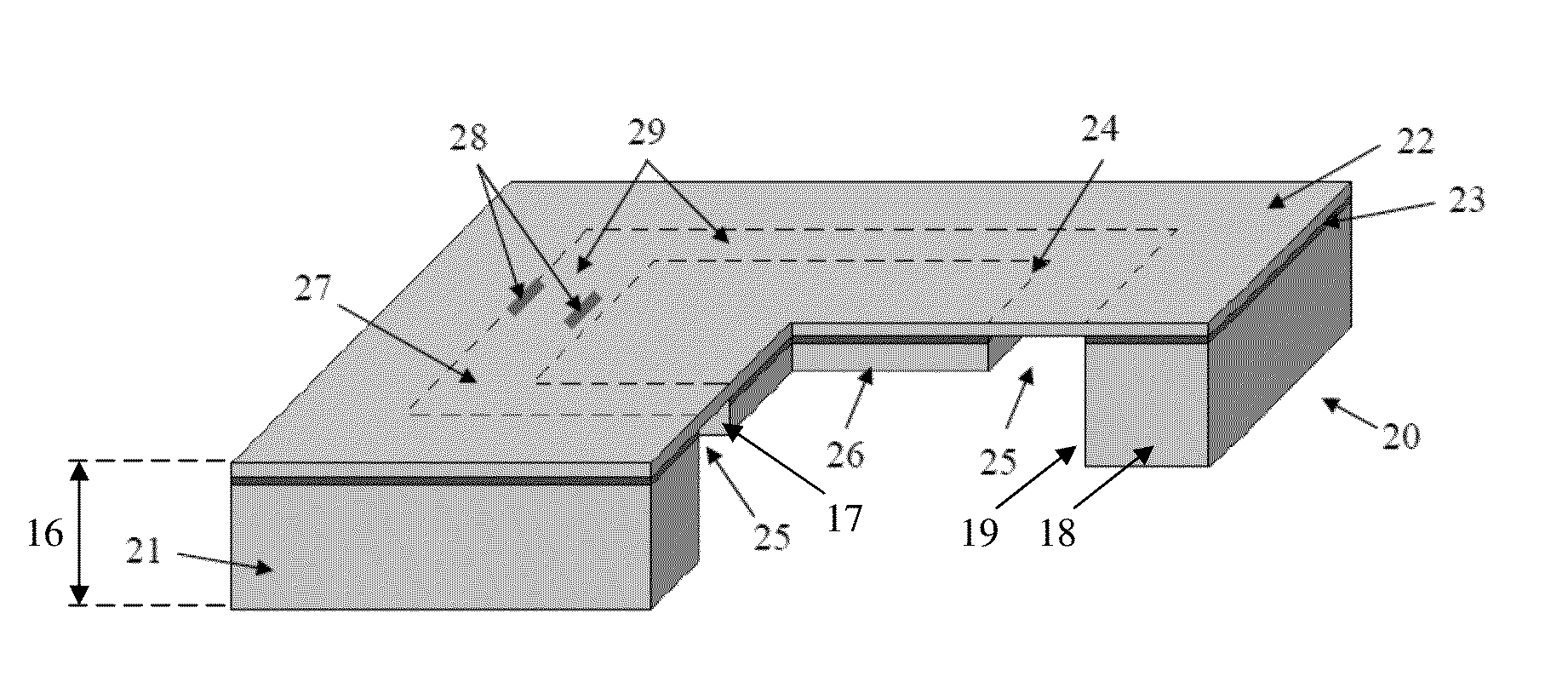
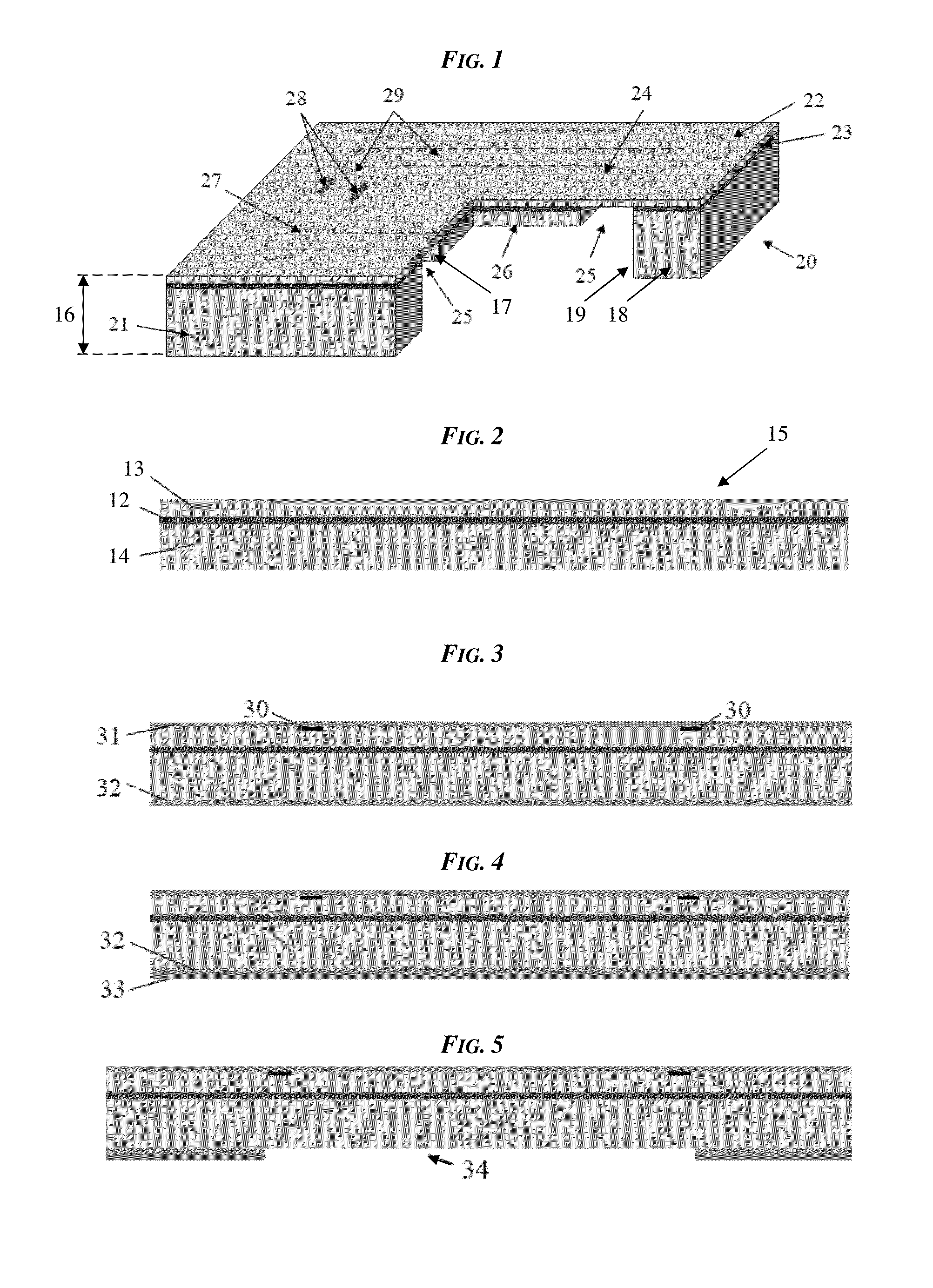
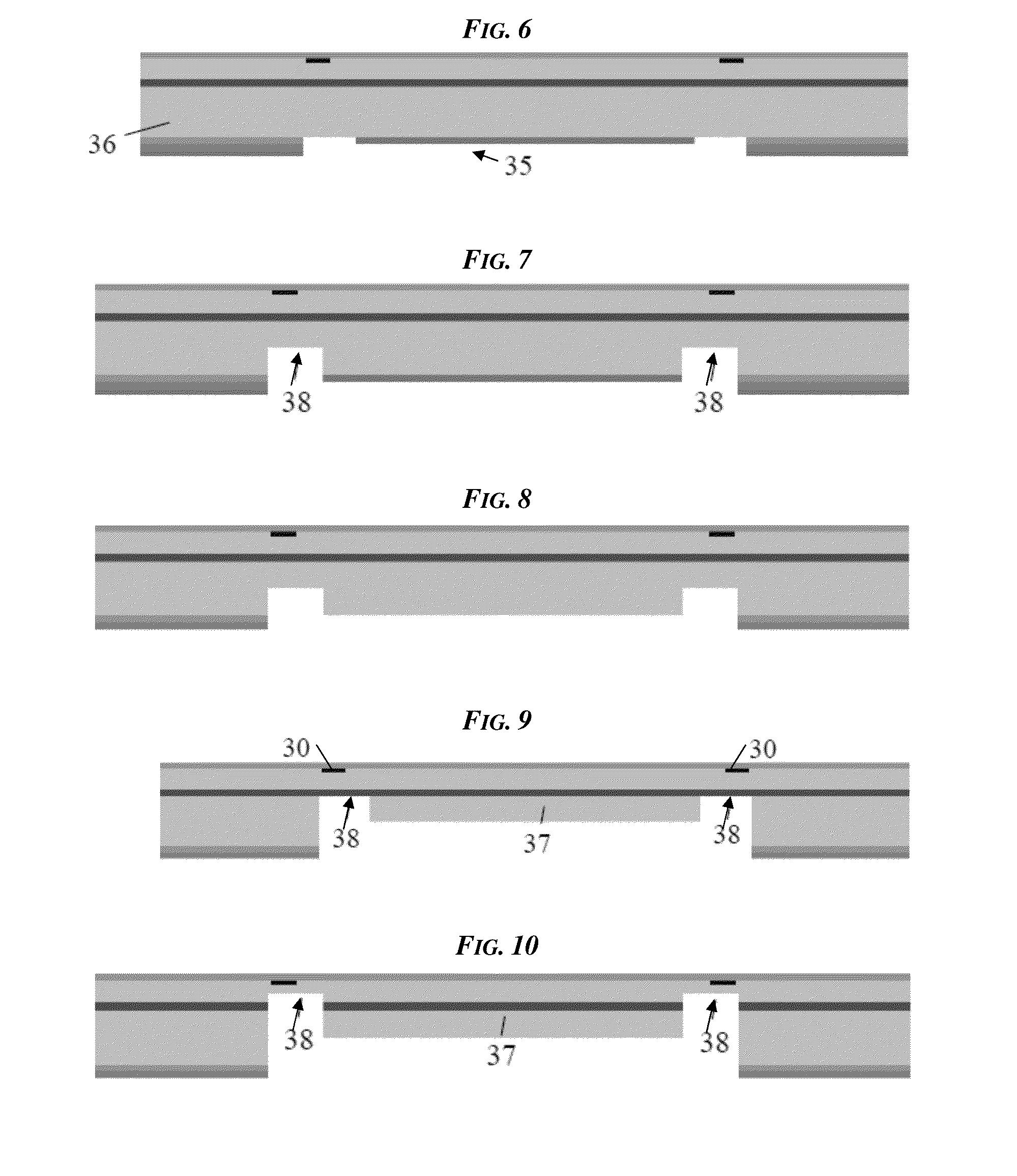
[0067]Certain exemplary embodiments will now be described to provide an overall understanding of the principles of the structure, function, manufacture, and use of the devices, systems, and methods disclosed herein. One or more examples of these embodiments are illustrated in the accompanying drawings. Those skilled in the art will understand that the devices, systems, and methods specifically described herein and illustrated in the accompanying drawings are non-limiting exemplary embodiments and that the scope of the present invention is defined solely by the claims. The features illustrated or described in connection with one exemplary embodiment may be combined with the features of other embodiments. Such modifications and variations are intended to be included within the scope of the present invention.

[0068]Various exemplary low pressure sensors and flow sensors are provided. In general, the low pressure sensors and flow sensors can be configured to sense pressure of an external...


PUM

PropertyMeasurementUnit
Thicknessaaaaaaaaaa
Lengthaaaaaaaaaa
Thicknessaaaaaaaaaa

Abstract

Low pressure sensors and flow sensors are provided. In some embodiments, a pressure sensor can include a sensor die that includes a substrate and a cavity that is formed in a bottom side of the substrate and that defines an elastic element including a thin diaphragm area and a rigid island. A maximum thickness of the rigid island can be substantially smaller than a thickness of the substrate and can be greater than a thickness of the thin diaphragm area. Side walls of the rigid island can be substantially parallel to one another and can be substantially perpendicular to top and bottom surfaces of the wafer and substantially perpendicular to top and bottom surfaces of the die. The side walls of the at least one rigid island can be formed by wet etching the cavity into the die. The wafer can have an impurity diffused in one or more portions thereof prior to the wet etching such that the one or more portions are doped.

Description

FIELD[0001]The subject matter disclosed herein relates to low pressure sensors and flow sensors.BACKGROUND[0002]Pressure sensors can be used in a variety of applications to sense and measure pressure. In some medical, industrial, automotive, aerospace, and other applications, a pressure sensor must be highly sensitive in order to be able to sense low pressure. High sensitivity low pressure sensors can be used in some applications for flow measurements.[0003]One type of pressure sensor that has been traditionally used for low pressure measurements is a silicon-based MEMS (MicroElectroMechanical Systems) piezoresistive pressure sensor. MEMS piezoresistive pressure sensors typically have a diaphragm and piezoresistors located on the diaphragm. When a pressure drop is applied to the diaphragm, the diaphragm bends, and resistance of the piezoresistors changes as a result of bending stress. Typically, the MEMS piezoresistive pressure sensor has four piezoresistors connected to a Wheatston...

Claims


Application Information

Patent Timeline
IPC IPC(8): G01L9/06B81C1/00G01L9/00
CPCG01L9/06B81C1/00158G01L9/0098G01L9/0044G01L9/0047G01L19/0092G01L19/0618B81B3/0072B81B2201/0264B81B2203/0127B81C2201/0133
Inventor BELOV, NICKOLAI S.LI, LIHUAVU, KIMVU, DINH
Owner AMPHENOL THERMOMETRICS
Why Eureka
Try Eureka