Field effect transistors for high-performance and low-power applications

a field effect transistor and high-performance technology, applied in the direction of transistors, electrical devices, semiconductor devices, etc., can solve the problems of affecting the performance of mos transistors, increasing the leakage current, and pronounced dependence of the threshold voltage on the channel length, so as to reduce the duration of a typical manufacturing cycle, and reduce the number of process steps

Inactive Publication Date: 2015-07-16
GLOBALFOUNDRIES INC
View PDF9 Cites 6 Cited by
  • Summary
  • Abstract
  • Description
  • Claims
  • Application Information

AI Technical Summary

Benefits of technology

[0030]The present disclosure generally provides manufacturing techniques for reducing the number of process steps for manufacturing high-performance and low-power field effect transistors of CMOS devices. A reduced number of process steps may be achieved by modifying the source and drain implantation processes so that source and drain extension region implantation processes and deep source and drain region implantation processes for a transistor may be replaced by a single source and drain implantation. Furthermore, the halo region implantation processes may be modified so that the threshold voltage of the transistors may be adjusted without a corresponding Vth well implantation step, wherein the electrical device behavior is substantially unmodified. In particular, the transistor performance and leakage characteristic is on the same level as the performance of conventional transistors, whereas the number of process steps for manufacturing high-performance and low-power field effect transistors is reduced and consequently the duration of a typical manufacturing cycle is reduced. Thus, the throughput of an available manufacturing environment is increased, resulting in reduced manufacturing costs. Furthermore, due to the reduced number of process steps for manufacturing high-performance and low-power field effect transistors, the periods of learning and adapting cycles for introducing amended CMOS devices and consequently the “time-to-market” is also reduced.
[0031]One illustrative method of forming a semiconductor device includes providing a substrate including a semiconductor layer and forming a gate electrode structure above an active region formed in the semiconductor layer. The method further comprises performing an implantation sequence using the gate electrode structure as a mask, wherein source and drain regions and halo regions of a field effect transistor are formed, and forming silicide regions within the source and drain regions.
[0032]A further illustrative method of forming a semiconductor device includes providing a substrate including a pre-doped semiconductor layer exhibiting an initial doping concentration and forming isolation regions defining an active region in the pre-doped semiconductor layer. The method further includes performing an implantation sequence implanting source and drain regions and halo regions of a field effect transistor into the active region exhibiting the initial doping concentration.
[0033]An illustrative semiconductor device includes a substrate including a semiconductor layer and a field effect transistor formed in and above the semiconductor layer. The field effect transistor includes a gate electrode formed above the semiconductor layer and source and drain regions formed in the semiconductor layer, wherein the shape of the source and drain regions is defined by a single source and drain implantation.

Problems solved by technology

Hence, the conductivity of the channel region substantially affects the performance of MOS transistors.
The short channel behavior may lead to an increased leakage current and to a pronounced dependence of the threshold voltage on the channel length.
Aggressively scaled transistor devices with a relatively low supply voltage and thus reduced threshold voltage may suffer from an exponential increase of the leakage current while also requiring enhanced capacitive coupling of the gate electrode to the channel region.
Although, generally, usage of high speed transistor elements having an extremely short channel may substantially be restricted to high speed signal paths, whereas transistor elements with a longer channel may be used for less critical signal paths, the relatively high leakage current caused by direct tunneling of charge carriers through an ultra-thin silicon dioxide gate insulation layer may reach values for an oxide thickness in the range of 1-2 nm that may not be compatible with thermal power design requirements for performance-driven circuits.
A retrograde channel dopant profile, however, is difficult to obtain due to inevitable diffusion effects.
Furthermore, any channel implantation increases lattice damage in the channel region.
Although the reduction of the gate length is beneficial for obtaining smaller and faster transistor elements, it turns out, however, that a plurality of issues are additionally involved to maintain proper transistor performance for a reduced gate length.
One challenging task in this respect is the provision of appropriate shallow junction regions, i.e., source and drain regions, which nevertheless exhibit a high conductivity so as to minimize the resistivity in conducting charge carriers from the channel to a respective contact area of the drain and source regions.
Thus, the dopants are located in a thin surface layer of the resist mask, which may impede the resist removal process and consequently increase the loss of material in the exposed regions so that the devices to be formed may be adversely affected, in particular devices requiring a high number of implantation and mask steps.

Method used


Image

  • Field effect transistors for high-performance and low-power applications
  • Field effect transistors for high-performance and low-power applications
  • Field effect transistors for high-performance and low-power applications

Examples


Embodiment Construction

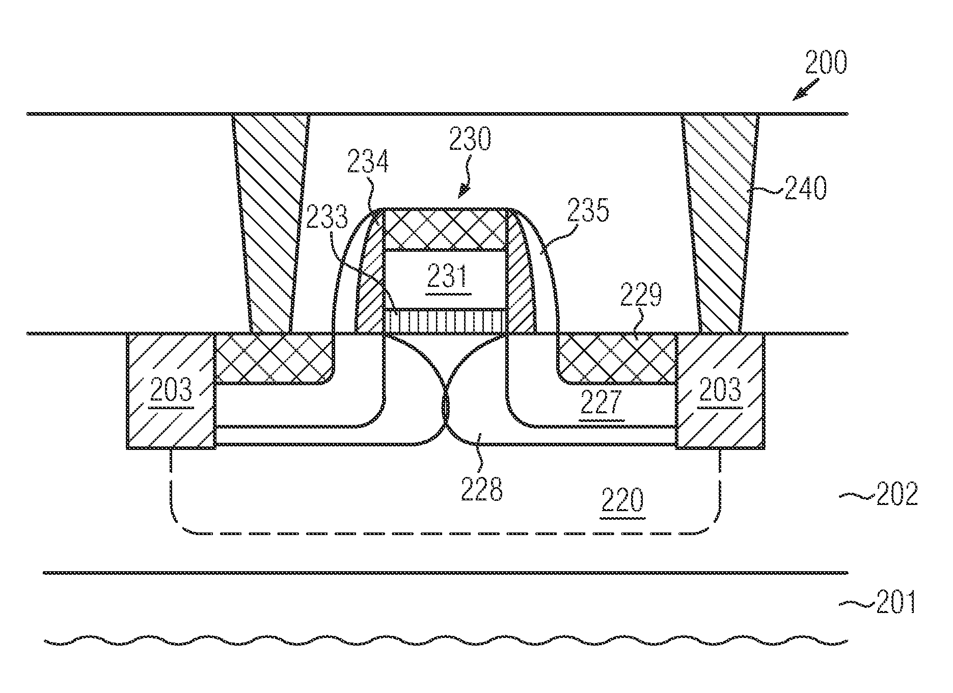
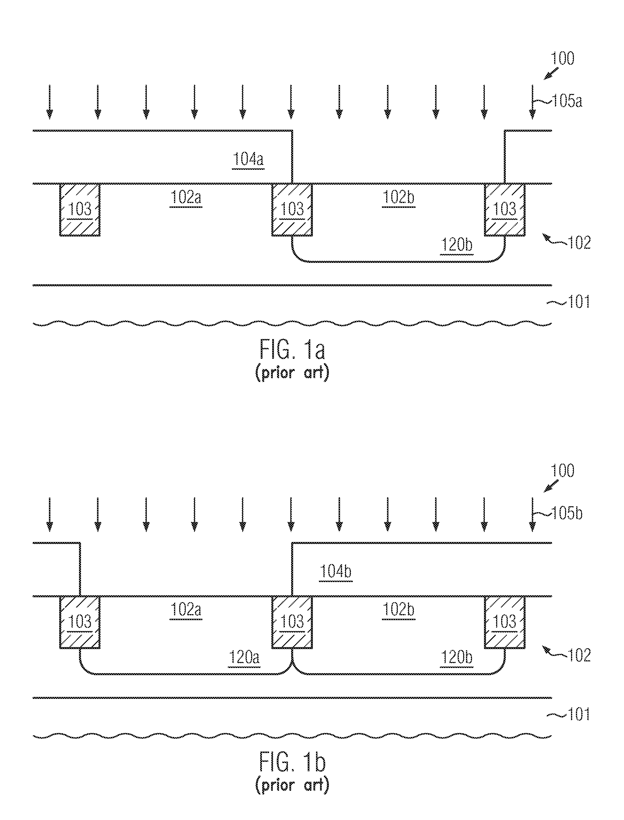
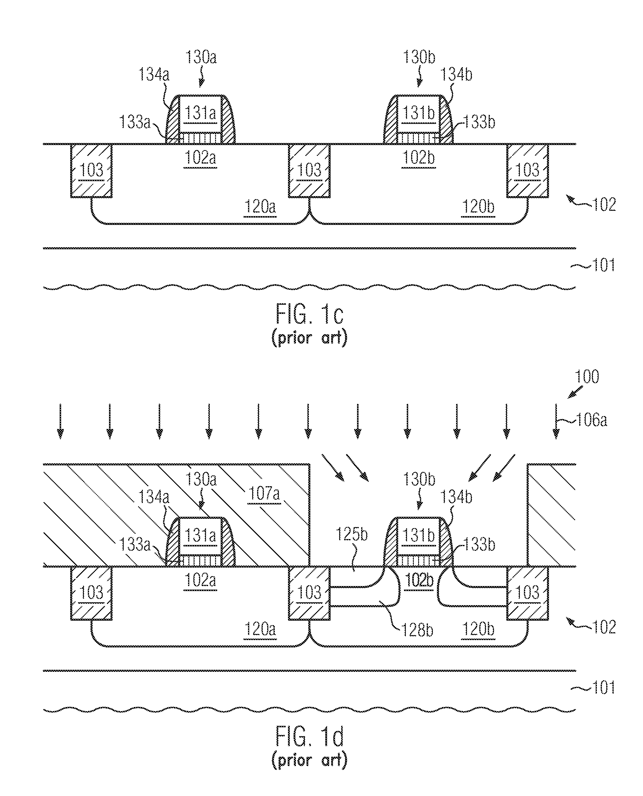
[0040]Various illustrative embodiments of the invention are described below. In the interest of clarity, not all features of an actual implementation are described in this specification. It will of course be appreciated that in the development of any such actual embodiment, numerous implementation-specific decisions must be made to achieve the developers' specific goals, such as compliance with system-related and business-related constraints, which will vary from one implementation to another. Moreover, it will be appreciated that such a development effort might be complex and time-consuming, but would nevertheless be a routine undertaking for those of ordinary skill in the art having the benefit of this disclosure.

[0041]The present disclosure will now be described with reference to the attached figures. Various structures, systems and devices are schematically depicted in the drawings for purposes of explanation only and so as to not obscure the present disclosure with details whic...


PUM

PropertyMeasurementUnit
gate lengthaaaaaaaaaa
depthaaaaaaaaaa
channel lengthaaaaaaaaaa

Abstract

When forming semiconductor devices comprising high performance or low-power field effect transistors, the threshold voltage of the transistors is adjusted by the halo implantation and the source and drain regions are defined by a single implantation step. Thus, the number of process steps is reduced, whereas the electrical characteristics, such as leakage level, and performance of the transistors are maintained compared to conventional transistors.

Description

BACKGROUND OF THE INVENTION[0001]1. Field of the Invention[0002]The present disclosure generally relates to the fabrication of integrated circuits, and, more particularly, to the fabrication of high-performance and low-power field effect transistors for low-cost CMOS devices.[0003]2. Description of the Related Art[0004]The fabrication of advanced integrated circuits, such as CPUs, storage devices, ASICs (application specific integrated circuits) and the like, requires the formation of a large number of circuit elements on a given chip area according to a specified circuit layout, wherein field effect transistors represent one important type of circuit element that substantially determines performance of the integrated circuits. Generally, a plurality of process technologies are currently practiced, wherein, for many types of complex circuitry including field effect transistors, CMOS technology is currently one of the most promising approaches due to the superior characteristics in v...

Claims


Application Information

Patent Timeline
Patent Type & Authority Applications(United States)
IPC IPC(8): H01L29/66H01L27/092H01L29/78H01L21/8238
CPCH01L29/66537H01L29/665H01L29/7816H01L21/823807H01L27/092H01L29/66575H01L21/823418H01L21/26586H01L29/66545H01L29/6656H01L29/1083
Inventor FLACHOWSKY, STEFANSACHSE, HERMANNWIATR, MACIEJ
Owner GLOBALFOUNDRIES INC
Why Eureka
Try Eureka