Bipolar alkaline water electrolysis unit and electrolytic cell

a technology of bipolar alkaline water and electrolysis cell, which is applied in the direction of electrolysis components, electrolysis processes, electrolysis coatings, etc., can solve the problems of high energy consumption, inability to put to practical use, and difficulty in producing a large electrolysis cell, so as to achieve convenient assembly and maintain the effect of facility costs

Active Publication Date: 2015-07-23
ASAHI KASEI KK
View PDF14 Cites 23 Cited by
  • Summary
  • Abstract
  • Description
  • Claims
  • Application Information

AI Technical Summary

Benefits of technology

[0060]According to the present invention, stable electrolysis can be performed at a low voltage in spite of a high current density usi

Problems solved by technology

Thus, the method has the disadvantage of having difficulty producing a large electrolytic cell.
Furthermore, the solid polymer electrolyte is highly acidic, and thus, a platinum-containing material needs to be used as a catalyst, and an expensive corrosion-resistant material needs to be used as a power feeder.
However, the electrolytic cell is mainly composed of a ceramic material, and thus, the method has a serious technical problem associated with high temperature operations and has not been put to practical use.
However, the method involves high energy consumption and thus, achieves only an approximately five to ten times lower current density than the “solid polymer water electrolysis”.
The method also still needs high electrolytic cell construction costs.
However, such renewable energy is not only locally biased but also involves a significant fluctuation in output.
Thus, transmission of power generated from natural energy to general power systems has limitations.
Another problem is that, for example, surplus power is generated as a result of a significant change in the amount of generated power depending on weather or season.
However, many problems need to be solved before an alkaline water electrolysis apparatus needing only low facility costs and providing high performance compared to conventional techniques is implemented using power such as renewable energy which fluctuates sharply in voltage or current within a short time.
Thus, a large number of electrolytic cells are provided, the facility is large in size, and the facility costs are high.
Furthermore, bipolar plates are used, and thus, when electrolysis is performed using an unstable power supply with a

Method used


Image

  • Bipolar alkaline water electrolysis unit and electrolytic cell
  • Bipolar alkaline water electrolysis unit and electrolytic cell
  • Bipolar alkaline water electrolysis unit and electrolytic cell

Examples


example 1

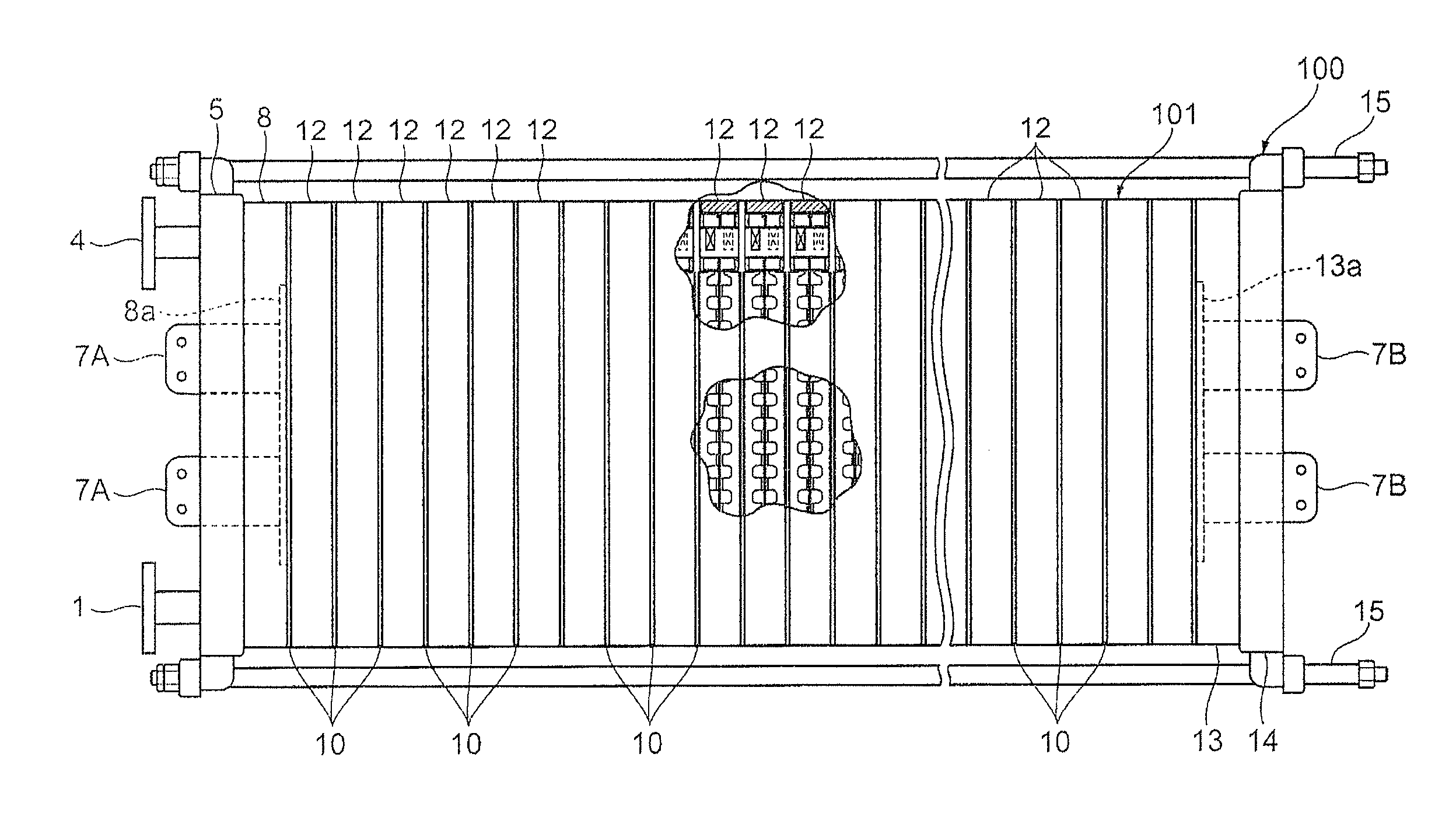
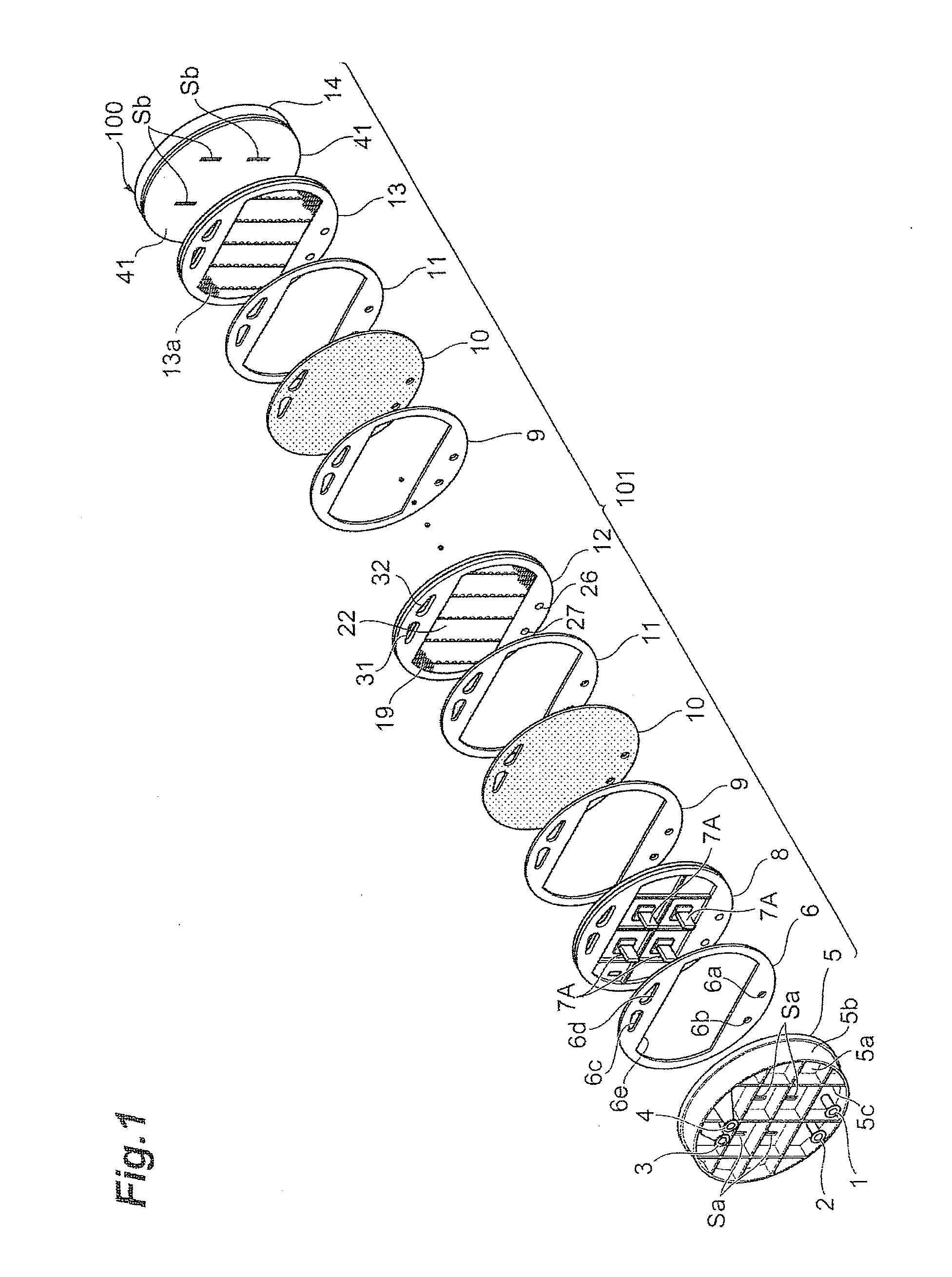
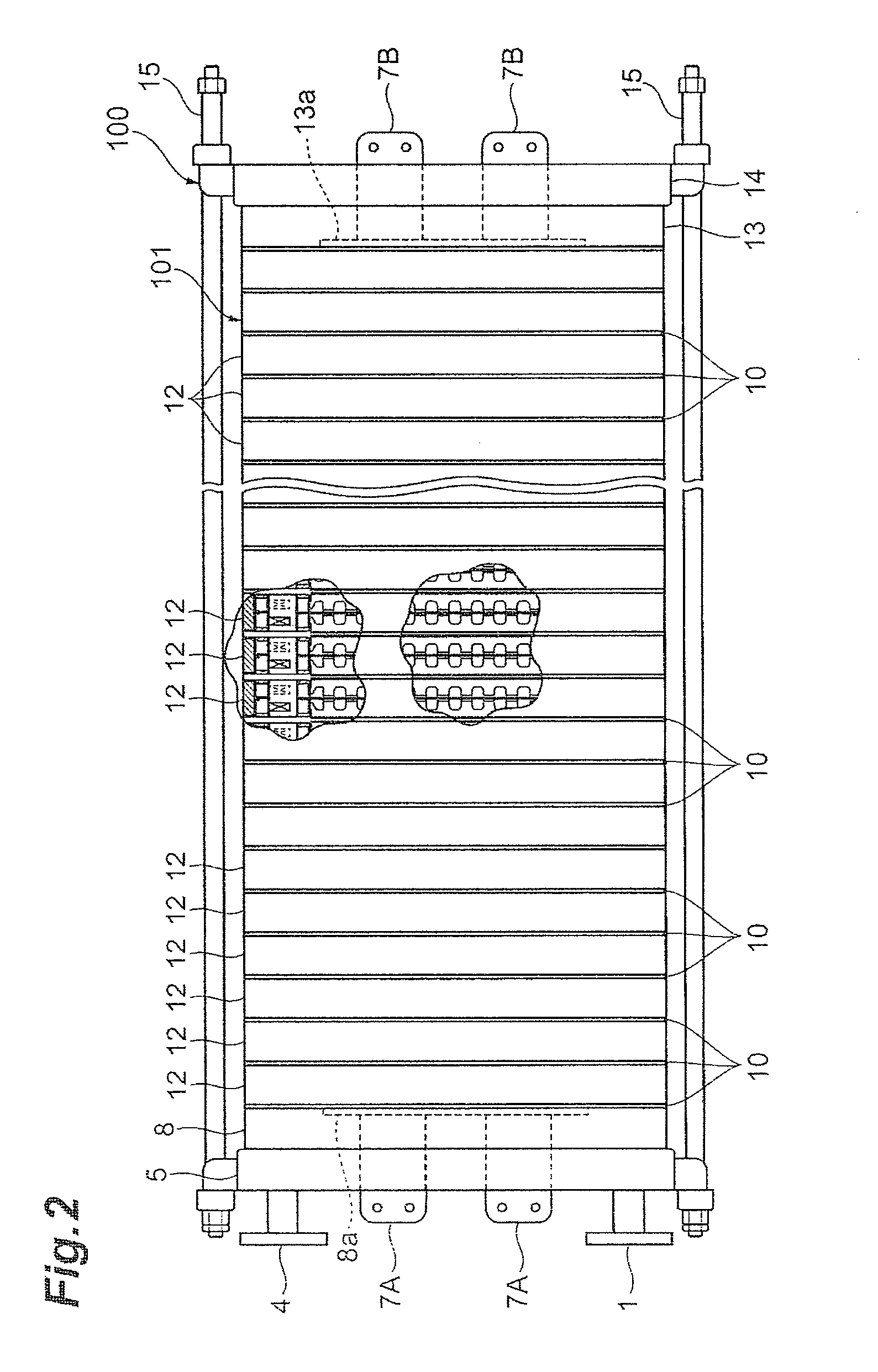
[0221]An electrolytic cell 100 similar to the one depicted in FIG. 2 was assembled by using three cells with electrolysis units 12 similar to those according to the first embodiment depicted in FIG. 3 and FIG. 4, and placing the press flange 5, the press flange gasket 6, and the anode terminal unit 8 at one end of the electrolytic cell, while arranging the end press flange 14 with the cathode terminal unit 13 and the insulating plate 41 attached thereto, at the other end, as depicted in FIG. 1.

[0222]The electrolysis unit 12 was shaped like a circle with an outer diameter of 700 mm, and the areas of the anode 18 and the cathode 19 were each 0.25 m2. Furthermore, the depth (anode chamber depth) of the anode chamber 103 was 15 mm, and the depth (cathode chamber depth) of the cathode chamber 105 was 15 mm. The materials for the anode side flange pan 23 and the cathode side flange pan 24 were each nickel. The nickel partition wall 22 to which the nickel anode rib 20 of height 15 mm and t...

example 3

[0234]An electrolytic cell 100 similar to the one depicted in FIG. 2 was assembled by using three cells with electrolysis units 120 similar to those according to the second embodiment depicted in FIGS. 8 to 10 instead of the electrolysis units 12, and placing the press flange 5, the press flange gasket 6, and the anode terminal unit 8 at one end of the electrolytic cell, while arranging the end press flange 14 with the cathode terminal unit 13 and the insulating plate 41 attached thereto, at the other end, as depicted in FIG. 1.

[0235]The electrolysis unit 12 was shaped like a circle with an outer diameter of 700 mm, and the areas of the anode 18 and the cathode 19 were each 0.25 m2. Furthermore, the depth (anode chamber depth) of the anode chamber 103 was 15 mm, and the depth (cathode chamber depth) of the cathode chamber 105 was 15 mm. The materials for the anode side flange pan 23 and the cathode side flange pan 24 were each nickel. The partition wall 22 to which the nickel anode ...

example 4

[0242]An electrolytic cell 100 similar to the one depicted in FIG. 2 was assembled by using three cells with electrolysis units 120 similar to those according to the fourth embodiment depicted in FIG. 9, FIG. 16, and FIG. 10 instead of the electrolysis units 12, and placing the press flange 5, the press flange gasket 6, and the anode terminal unit 8 at one end of the electrolytic cell, while arranging the end press flange 14 with the cathode terminal unit 13 and the insulating plate 41 attached thereto, at the other end, as depicted in FIG. 1.

[0243]The electrolysis unit 120 was shaped like a circle with an outer diameter of 700 mm, and the areas of the anode 18 and the cathode 19 were each 0.25 m2. Furthermore, the depth (anode chamber depth) of the anode chamber 103 was 15 mm, and the depth (cathode chamber depth) of the cathode chamber 105 was 15 mm. The nickel anode rib 20 of height 15 mm and thickness 1.5 mm and the nickel cathode rib 21 of height 13.5 mm and thickness 1.5 mm we...


PUM

PropertyMeasurementUnit
Temperatureaaaaaaaaaa
Lengthaaaaaaaaaa
Fractionaaaaaaaaaa

Abstract

A bipolar alkaline water electrolysis unit incorporated in an electrolytic cell for electrolyzing an electrolytic solution of alkaline water to obtain oxygen and hydrogen, the bipolar alkaline water electrolysis unit including an oxygen generating anode, a hydrogen generating cathode, a conductive partition wall that separates the anode and the cathode from each other, and an outer frame that surrounds the conductive partition wall, wherein a gas and electrolytic solution passage is provided at an upper portion of the conductive partition wall and/or the outer frame, and an electrolytic solution passage is provided at a lower part of the conductive partition wall and/or the outer frame.

Description

TECHNICAL FIELD[0001]The present invention relates to a bipolar alkaline water electrolysis unit incorporated in an electrolytic cell for obtaining oxygen and hydrogen by electrolyzing an electrolytic solution of alkaline water, and the electrolytic cell. More specifically, the present invention relates to an inexpensive, energy-efficient bipolar alkaline water electrolysis unit for obtaining oxygen from an anode side and hydrogen from a cathode side using an electrolytic solution including NaOH or KOH and the like, and the electrolytic cell.BACKGROUND ART[0002]Examples of a water electrolysis method include “solid polymer water electrolysis” in which an anode catalyst and a cathode catalyst are coated on a solid polymer electrolyte, “high-temperature steam electrolysis” in which electrolysis is performed at high temperature and with high-temperature steam using a solid electrolyte of an oxygen ion conductor, and “alkaline water electrolysis” which uses a water solution of KOH or a ...

Claims


Application Information

Patent Timeline
IPC IPC(8): C25B11/03C25B11/04C25B1/10C25B9/19
CPCC25B11/035C25B11/0447C25B1/10Y02E60/36C25B1/04C25B9/73C25B11/031C25B11/075
Inventor NOAKI, YASUHIDEUCHINO, YOUSUKEMIYOSHI, KEIJI
Owner ASAHI KASEI KK
Why Eureka
Try Eureka