Sinter mold material, sintering and molding method, sinter mold object, and sintering and molding apparatus

a mold object and sintering technology, applied in auxillary shaping apparatus, butter manufacture, chemical/physical processes, etc., can solve the problems of inferior strength of powder material, . 2729110, and the inability to stabilize the forming of high-precision mold objects with greater strength

Inactive Publication Date: 2015-08-13
SEIKO EPSON CORP
View PDF7 Cites 50 Cited by
  • Summary
  • Abstract
  • Description
  • Claims
  • Application Information

AI Technical Summary

Benefits of technology

[0018]According to the present applied example, it is possible for degreasing where the second thermoplastic binder is the target to progress by heating the sinter mold material at a temperature which exceeds the temperature of the initial temperature of thermal decomposition (from 350° C. to 750° C.) of polyethylene, polypropylene, polytetrafluoroethylene, or polybenzimidazole.
[0042]According to the present applied example, the sinter mold object is configured to include the first inorganic particles which are included beforehand in the sinter mold material which is to be layered and the second inorganic particles which are included in the liquid droplets which are applied to the sinter mold material which is layered. That is, since the sinter mold object is configured to include the second inorganic particles in addition to the first inorganic particles, it is possible to obtain the sinter mold object where the filling ratio of the inorganic particles is higher compared to a sinter mold object which is configured only by the first inorganic particles.

Problems solved by technology

The strength of the mold object in manufacturing methods, where the powder material is connected together using a liquid binding agent as in Japanese Patent No. 2729110, is typically inferior.
That is, there are problems in the mold object manufacturing method in Japanese Patent No. 2729110 in that it is not possible to stabilize forming of a high precision mold object with greater strength.

Method used


Image

  • Sinter mold material, sintering and molding method, sinter mold object, and sintering and molding apparatus
  • Sinter mold material, sintering and molding method, sinter mold object, and sintering and molding apparatus
  • Sinter mold material, sintering and molding method, sinter mold object, and sintering and molding apparatus

Examples


embodiment 1

[0049]As embodiment 1, a “sinter mold material”, a “sintering and molding apparatus”, and a “sintering and molding method” which uses the sinter mold material and the sintering and molding apparatus will be described with respect to layer molding as one technique of molding a three dimensional solid model (a sinter mold object). As the method for layer molding, a method is used where a mold object is formed by selectively applying liquid droplets using an ink jet system to a thin layer which is configured by a sinter mold material which is to be formed into the cross sectional shape of the mold object and consecutively layering the portions where the liquid droplets are applied while curing.

[0050]Below, the details of this will be described.

Sinter Mold Material

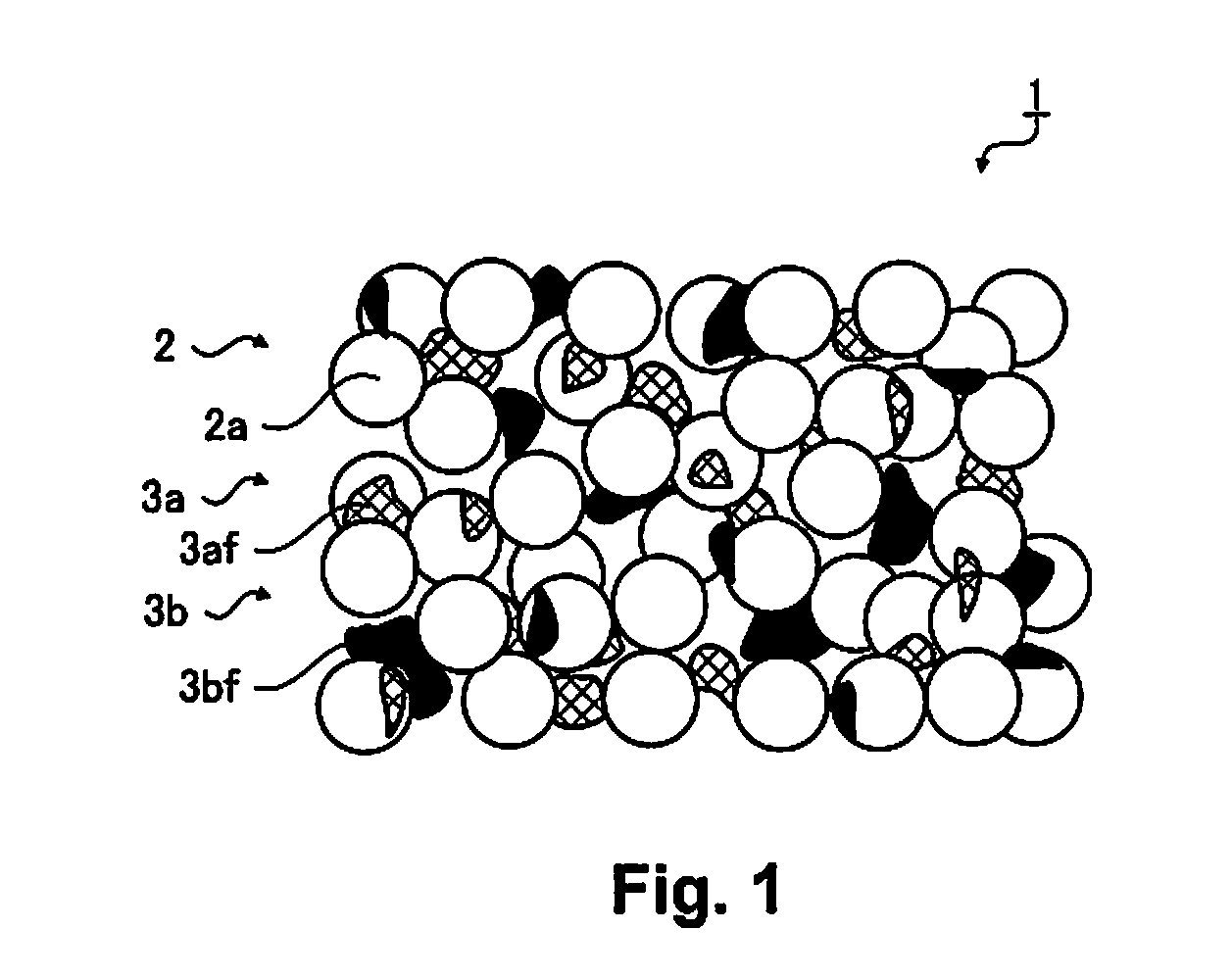
[0051]FIG. 1 is a conceptual diagram illustrating a state of a sinter mold material 1 according to an embodiment at room temperature (15° C. to 25° C.).

[0052]The sinter mold material 1 is a material (principal component) which...

applied example

[0073]The sinter mold material 1 according to the present embodiment is formed by kneading a stainless steel alloy powder as (A) the powder material 2, polyvinyl alcohol as (B) the binder material 3a, polyethlene as (C) the binder material 3b, and a mixture liquid of water and tetrahydrofuran as (D) the water-based solvent with a volume ratio of (A):(B):(C):(D)=6.2:045:0.05:3.3.

Sintering and Molding Apparatus

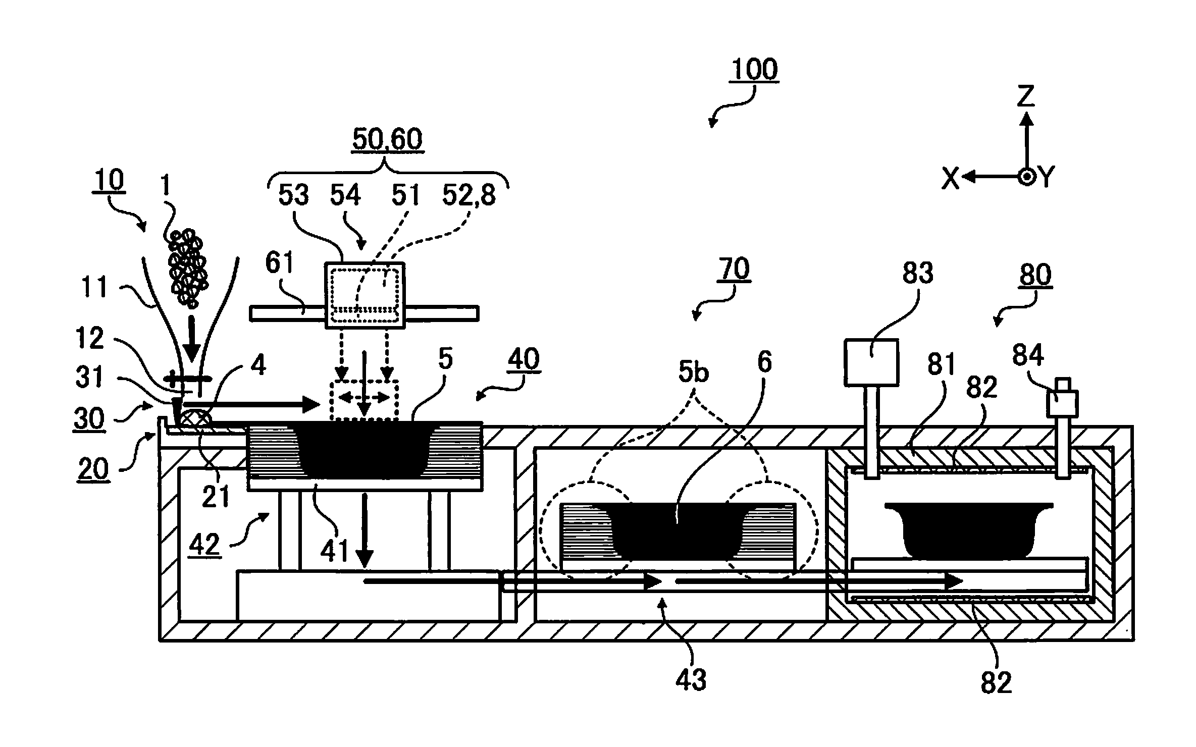
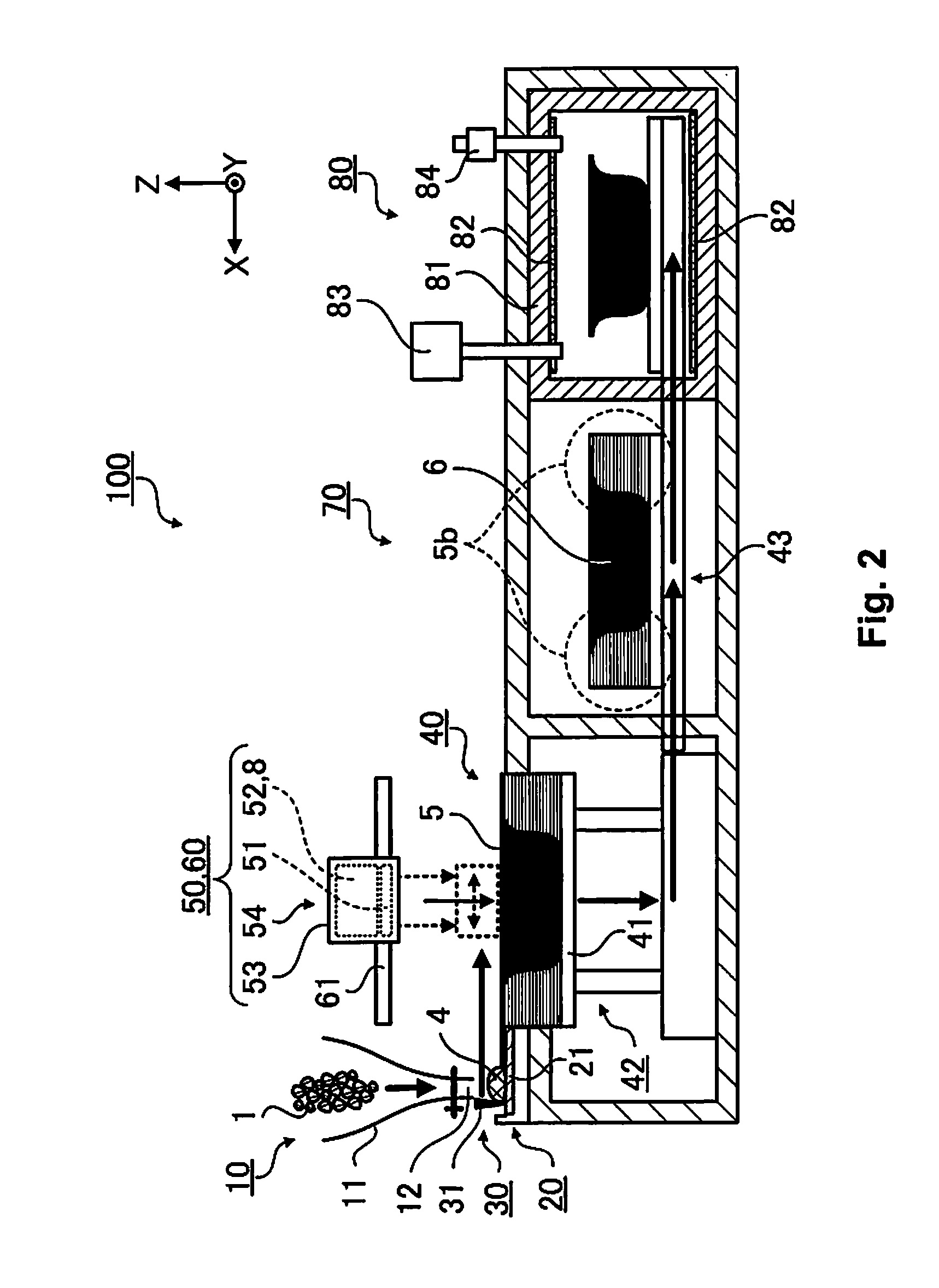
[0074]FIG. 2 is a schematic diagram for describing a sintering and molding apparatus 100 according to the present embodiment.

[0075]In FIG. 2, the Z axis direction is the up and down direction and the −Z direction is the vertical direction, the Y axis direction is the front and back direction and the +Y direction is the forward direction, the X axis direction is the left and right direction and the +X direction is the leftward direction, and the X-Y plane is a plane which is parallel with the plane on which the sintering and molding apparatus 100 is arranged.

[0076]The sintering a...

embodiment 2

[0136]A sintering and molding method and a sinter mold object according to embodiment 2 will be described next. Here, in the description, the same reference numerals are used for the configuration parts which are the same as the embodiment described above and overlapping description is omitted.

[0137]Embodiment 2 is where “liquid droplets” includes “second organic particles”. The sintering and molding method of embodiment 2 only differs with regard to the point where UV ink 9 is used as the UV ink 8 which is used in embodiment 1 and the other configuration parts are the same as the sintering and molding method of embodiment 1.

[0138]FIG. 4 is a conceptual diagram illustrating a situation where the UV ink 9 is applied as the “liquid droplets” which include second inorganic particles 2b as the “second organic particles” in contrast to FIG. 3 which illustrates a situation where the UV ink 8 is applied to a desired region of the mold layer 5.

[0139]The UV ink 9 is ultraviolet ray curable i...


PUM

PropertyMeasurementUnit
temperatureaaaaaaaaaa

Abstract

A sintering and molding method includes forming a fluid mold material by heating a sinter mold material, which includes inorganic particles, a binder material and a binder material which bond together the inorganic particles, to a temperature equal to or more than the melting points of the binder materials, forming a mold layer by spreading the fluid mold material, layering a mold layer, applying UV ink to a desired region on the mold layer, forming a mold cross sectional pattern by curing the UV ink which is applied to a desired region on the mold layer, finishing a mold object by removing a region, where the UV ink is not applied, in the mold layer, carrying out heat treatment on the mold object at a temperature which is less than the initial temperature of thermal decomposition of the binder material, and carrying out sintering treatment on the mold object.

Description

CROSS-REFERENCE TO RELATED APPLICATIONS[0001]This application claims priority to Japanese Patent Application No. 2014-022002 filed on Feb. 7, 2014. The entire disclosure of Japanese Patent Application No. 2014-022002 is hereby incorporated herein by reference.BACKGROUND[0002]1. Technical Field[0003]The present invention relates to a sinter mold material, a sintering and molding method, a sinter mold object, and a sintering and molding apparatus.[0004]2. Related Art[0005]There is a layer molding method as one method for molding where a solid model (a mold object) with a three dimensional shape is formed. As a layering and molding method, there are proposed, for example, a light molding method where each layer of a cross section of a mold object is formed by selectively curing a photocurable resin using a laser while layering, a powder sintering method where each layer is formed by selectively fusing and solidifying a powder material using a laser while layering, a molten depositing m...

Claims


Application Information

Patent Timeline
Patent Type & Authority Applications(United States)
IPC IPC(8): B22F1/00B22F3/105C04B35/634B22F3/00B28B1/00B28B11/24B22F1/103
CPCB22F1/0059B33Y70/00B28B11/243C04B35/63416C04B35/63424C04B35/63436C04B35/63444C04B35/63408C04B35/63404B22F3/003B22F3/1055B22F2001/0066B33Y10/00B33Y30/00B28B1/001B28B7/465C04B35/111C04B35/486C04B35/638C04B2235/528C04B2235/5436C04B2235/5445B22F2998/10Y02P10/25B22F1/103B22F12/52B22F12/41B22F10/12B33Y70/10B22F3/1021B22F10/10
Inventor HIRATA, KOKI
Owner SEIKO EPSON CORP
Why Eureka
Try Eureka