Piezoelectric device, piezoelectric actuator, hard disk drive, and inkjet printer apparatus

a piezoelectric actuator and actuator technology, applied in the field of piezoelectric actuators, hard disk drives, inkjet printers, etc., can solve the problems of high piezoelectric element polarization degradation and durability degradation, and achieve the effect of piezoelectric actuator output and high-performance hard disk drives

Active Publication Date: 2015-08-13
TDK CORPARATION
View PDF7 Cites 4 Cited by
  • Summary
  • Abstract
  • Description
  • Claims
  • Application Information

AI Technical Summary

Benefits of technology

The invention is related to a piezoelectric actuator technology that reduces polarization degradation during continuous driving, even at high temperature and pressure. The technology uses a constantly positive electric field to apply to the piezoelectric material, but it was found that this method does not work well with thin film piezoelectric layers. Instead, the piezoelectric layer is designed to have a coercive electric field on each side, and the driving circuit applies an electric field in a way that maximizes the displacement of the piezoelectric layer. This results in greater displacement of the piezoelectric layer, even at low electric field levels. This technology can improve the performance of hard disk drives and ink-jet printers.

Problems solved by technology

However, there are problems that, for example, a piezoelectric material showing hysteresis with a small squareness ratio does not have sufficient piezoelectric characteristics depending on the condition of the applied electric field and possibilities of occurrences of polarization degradation and durability degradation due to continuous drive of a piezoelectric element are high.
However, this method is on the assumption that the piezoelectric material is a bulk piezoelectric material, and if this method is applied to a thin film piezoelectric layer, the film is broken easily even when an electric field not causing polarization degradation of the piezoelectric layer is applied.

Method used


Image

  • Piezoelectric device, piezoelectric actuator, hard disk drive, and inkjet printer apparatus
  • Piezoelectric device, piezoelectric actuator, hard disk drive, and inkjet printer apparatus
  • Piezoelectric device, piezoelectric actuator, hard disk drive, and inkjet printer apparatus

Examples


example 1

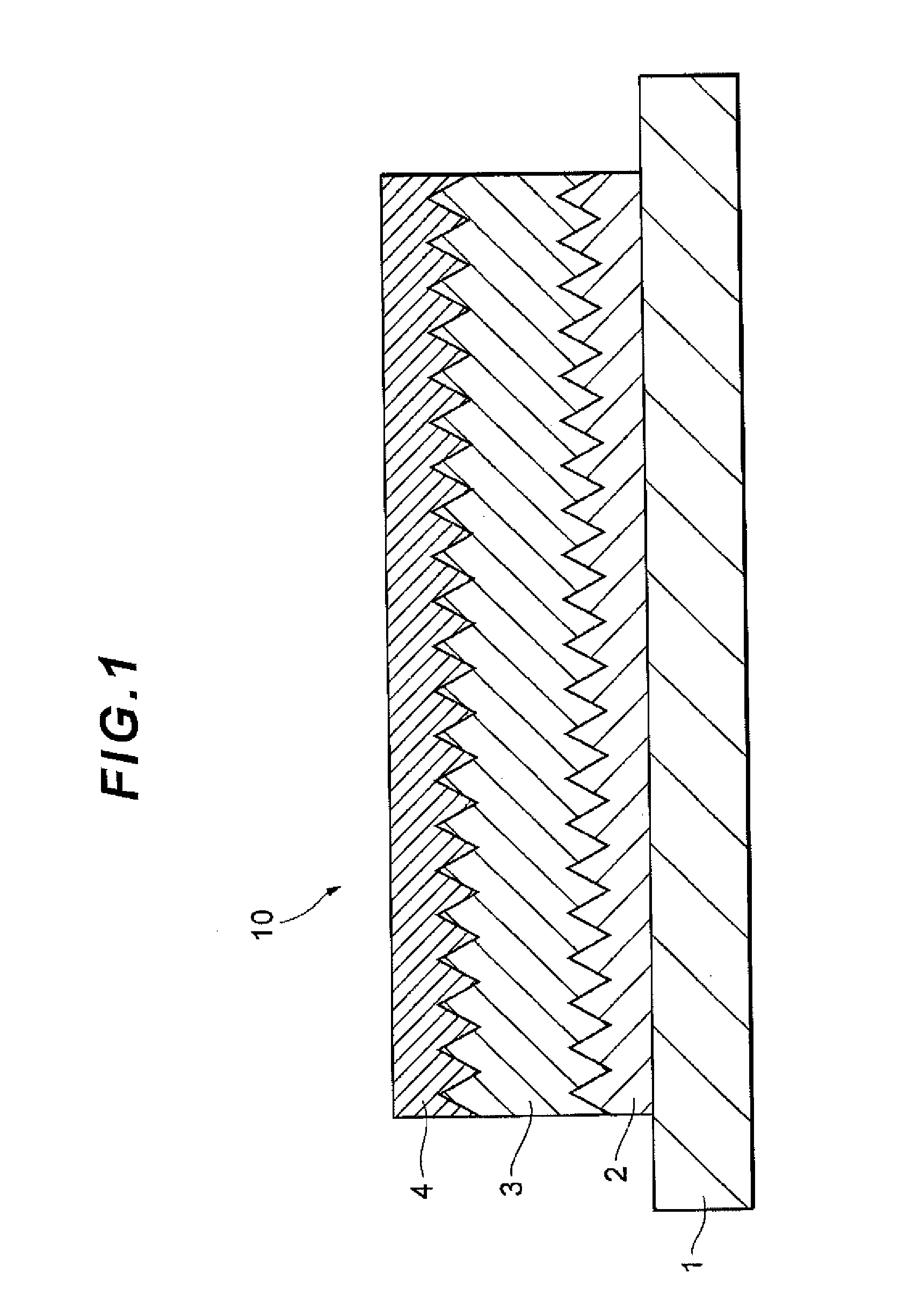
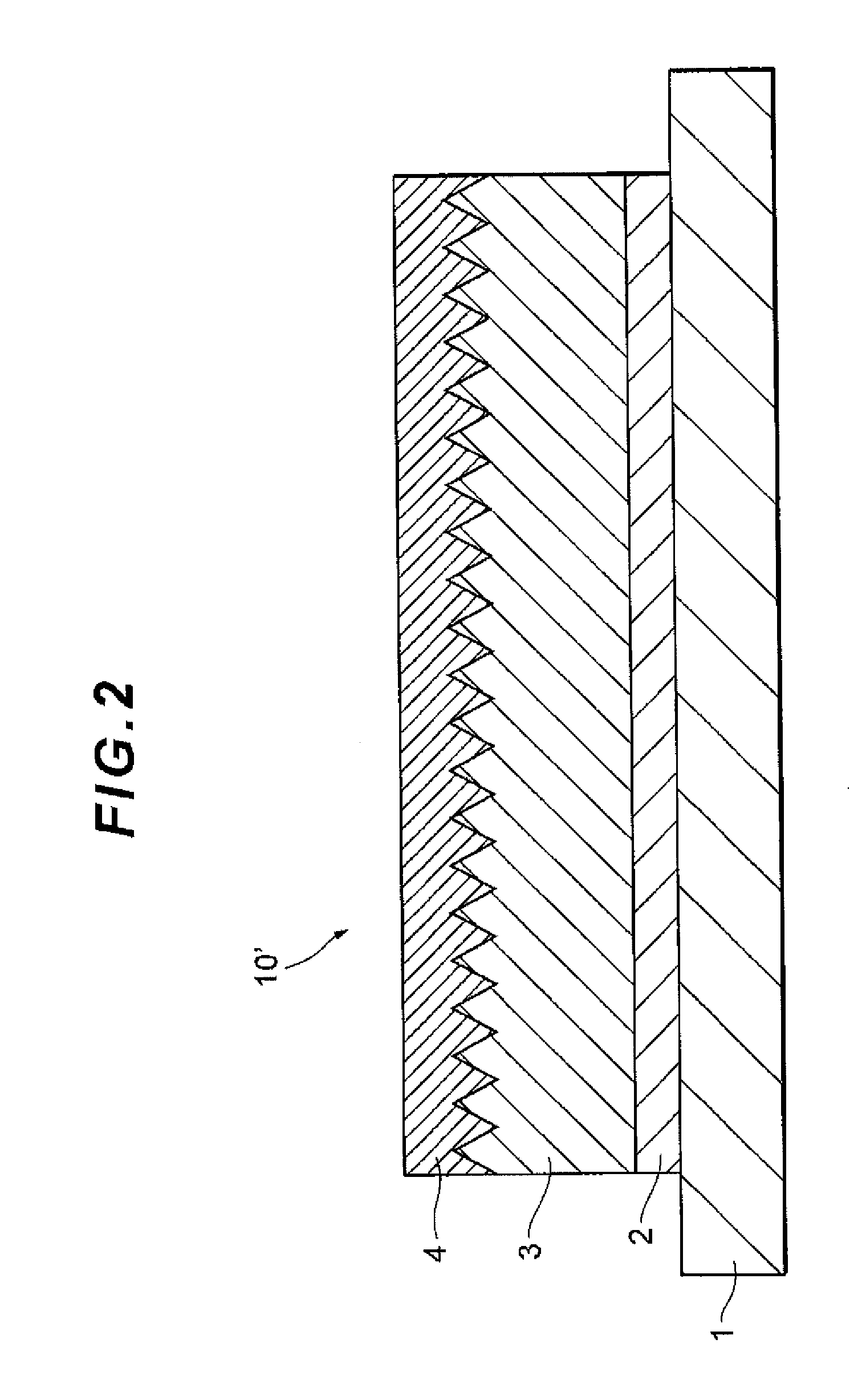
[0078]Initially, the first electrode layer 81 serving as a substrate film of the piezoelectric layer 82 was obtained through crystal growth on a 3-inch substrate which is single crystal Si. This first electrode layer 81 was a Pt film and the film thickness was specified to be 0.2 μm. The forming method was a sputtering method and the film formation was performed while the substrate was heated to 500° C.

[0079]Subsequently, a sputtering target having a (K0.5Na0.5)NbO3 (potassium-sodium niobate) composition was used, and a film of the piezoelectric layer 82 was formed on the first electrode layer 81. The forming method was a sputtering method and, as with the first electrode layer 81, the film formation was performed under the condition in which the substrate was specified to be 7500° C. The film thickness was specified to be 2.0 μm (KNN1).

[0080]Then, a Pt film was formed as the second electrode layer 83 on the piezoelectric layer 82. The forming method was the sputtering method as wit...

example 2

[0089]A piezoelectric device 1 in Example 2 was formed by using a piezoelectric element 80 having the same characteristics as those in Example 1. At this time, the magnitudes of two coercive electric fields obtained in measurement of the P-E hysteresis by the current monitoring circuit 30 in the piezoelectric device 1 were examined, and contrary to the setting in Example 1, of the two, the coercive electric field having a small absolute value was specified to be Ec+, the application direction of Ec+ was specified to be the positive electric field direction, and the piezoelectric constant was determined in the same manner as that in Example 1.

example 3

[0090]The piezoelectric constant of the same piezoelectric device 1 as that in Example 2 was determined in the same manner as that in Example 1, where setting was performed in such a way that Emin and Emax were limited to more than or equal to 5 times the Ec+ and less than or equal to 50 times the Ec+, respectively, on the basis of the lower limit value Ell and the upper limit value Eul obtained from the current monitoring circuit 30.


PUM


Abstract

A piezoelectric device is provided with a piezoelectric element including a piezoelectric layer exhibiting a polarizability γ smaller than 1×10⁻⁹ (C / (V·m)) in the case where an electric field is applied until polarization is saturated and a circuit having a means to set a minimum value of a drive electric field to become larger than a positive coercive electric field of the above-described piezoelectric layer and a means to set a maximum value of the above-described drive electric field to become smaller than (Pm′ (maximum value of polarization)−Pr′ (quasi-remanent polarization)) / (1×10⁻⁹) and, therefore, an object is to drive the piezoelectric element in an electric field range in which maximum piezoelectric characteristics are obtained, improve the characteristics of the piezoelectric device, and enhance the reliability.

Description

BACKGROUND OF INVENTION[0001]1. Field of Invention[0002]The present invention relates to a piezoelectric device provided with a piezoelectric element including a piezoelectric layer and a drive circuit to control a drive electric field applied to the piezoelectric layer, a piezoelectric actuator by using the piezoelectric device, and a hard disk drive provided with the piezoelectric actuator and an ink-jet printer apparatus.[0003]2. Background Art[0004]In recent years, instead of bulk piezoelectric materials, commercialization of a piezoelectric element by using a thin film piezoelectric material has proceeded. Examples include piezoelectric sensors taking advantage of a piezoelectric effect, in which a force applied to a piezoelectric layer is converted to a voltage, e.g., a gyro sensor, a pressure sensor, a pulse wave sensor, a shock sensor, and a microphone, piezoelectric actuators taking advantage of an inverse piezoelectric effect, in which a piezoelectric layer is deformed whe...

Claims


Application Information

Patent Timeline
Patent Type & Authority Applications(United States)
IPC IPC(8): H02N2/00H01L41/187
CPCH01L41/1873H02N2/0075H10N30/802H10N30/2047H10N30/8542B06B2201/55B06B1/0253H02N2/14
Inventor HIROSE, YUIKOAIDA, YASUHIRO
Owner TDK CORPARATION
Why Eureka
Try Eureka