
Manufacturing method of conductive sheet and conductive sheet

Active Publication Date: 2015-08-20
FUJIFILM CORP
View PDF5 Cites 7 Cited by
  • Summary
  • Abstract
  • Description
  • Claims
  • Application Information

AI Technical Summary

Benefits of technology

The patent text discusses the issue of ion migration in conductive sheets, which can lead to conduction between neighboring wirings and cause damage to products requiring high performance and miniaturization. The invention provides a conductive sheet with reduced ion migration between conductive portions and a manufacturing method for it. This provides a solution for inhibiting damage caused by ion migration and improving the reliability of conductive sheets in various applications.

Problems solved by technology

However, in a case in which the wiring interval has been narrowed as described above, the method described in JP 2010-205927 A does not necessarily bring about a sufficient effect, and accordingly, the method needs to be further improved.
Moreover, even when the enzyme described in JP 4895536 B is used, a sufficient effect is not necessarily exerted, and accordingly, the method needs to be further improved.

Method used


Image

  • Manufacturing method of conductive sheet and conductive sheet
  • Manufacturing method of conductive sheet and conductive sheet
  • Manufacturing method of conductive sheet and conductive sheet

Examples


example 1

Preparation of Silver Halide Emulsion

[0314]To the following liquid 1 held at 38° C. and pH 4.5, the following liquid 2 and liquid 3 were simultaneously added for 20 minutes while being stirred, thereby forming nuclear particles having a particle size of 0.16 μm. At this time, each of the liquid 2 and liquid 3 was used in an amount corresponding to 90% of the amount thereof. Thereafter, the following liquid 4 and liquid 5 were added thereto for 8 minutes. Then, the balance of 10% of the following liquid 2 and liquid 3 was added thereto for 2 minutes, and particles were allowed to grow up to 0.21 μm. Moreover, 0.15 g of potassium iodide was added thereto, the resultant was aged for 5 minutes, and then the formation of particles was ended.

[0315]Liquid 1:

Water750 mlGelatin8.6 gSodium chloride  3 g1,3-Dimethylimidazolidine-2-thione20 mgSodium benzene thiosulfonate10 mgCitric acid0.7 g

[0316]Liquid 1:

Water300 mlSilver nitrate150 g

[0317]Liquid 3:

Water300 mlSodium chloride38 gPotassium bromi...

example 2

[0382]Samples were prepared and subjected to various evaluations according to the same procedure as in Example 1, except that the following (Reduction treatment) was performed after the aforementioned (Gelatin decomposition treatment). The results are summarized in Table 1.

[0383](Reduction Treatment)

[0384]The samples were dipped into the following reduction treatment solution for 360 seconds, and then washed with pure water.

[0385](Composition of Reduction Treatment Solution)

[0386]1 L of the reduction treatment solution contained the following compounds.

Hydroquinone0.20 mol / LPotassium hydroxide0.45 mol / LPotassium carbonate0.24 mol / L

example 3

[0387]Samples were prepared and subjected to various evaluations according to the same procedure as in Example 2, except that in the silver halide-containing photosensitive layer, the mixing ratio (polymer / gelatin) of the polymer to the gelatin was changed to 1 / 1 from 0.5 / 1 in terms of mass, and the content of the polymer was changed to 0.44 g / m2 from 0.22 g / m2. The results are summarized in Table 1.


PUM

PropertyMeasurementUnit
surface roughnessaaaaaaaaaa
thicknessaaaaaaaaaa
thicknessaaaaaaaaaa

Abstract

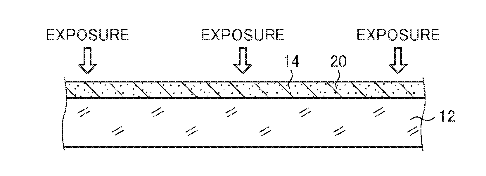
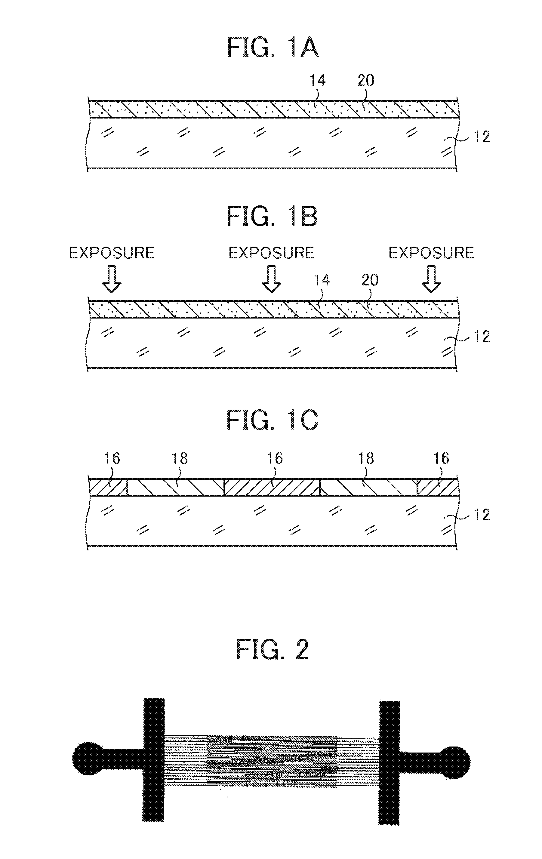
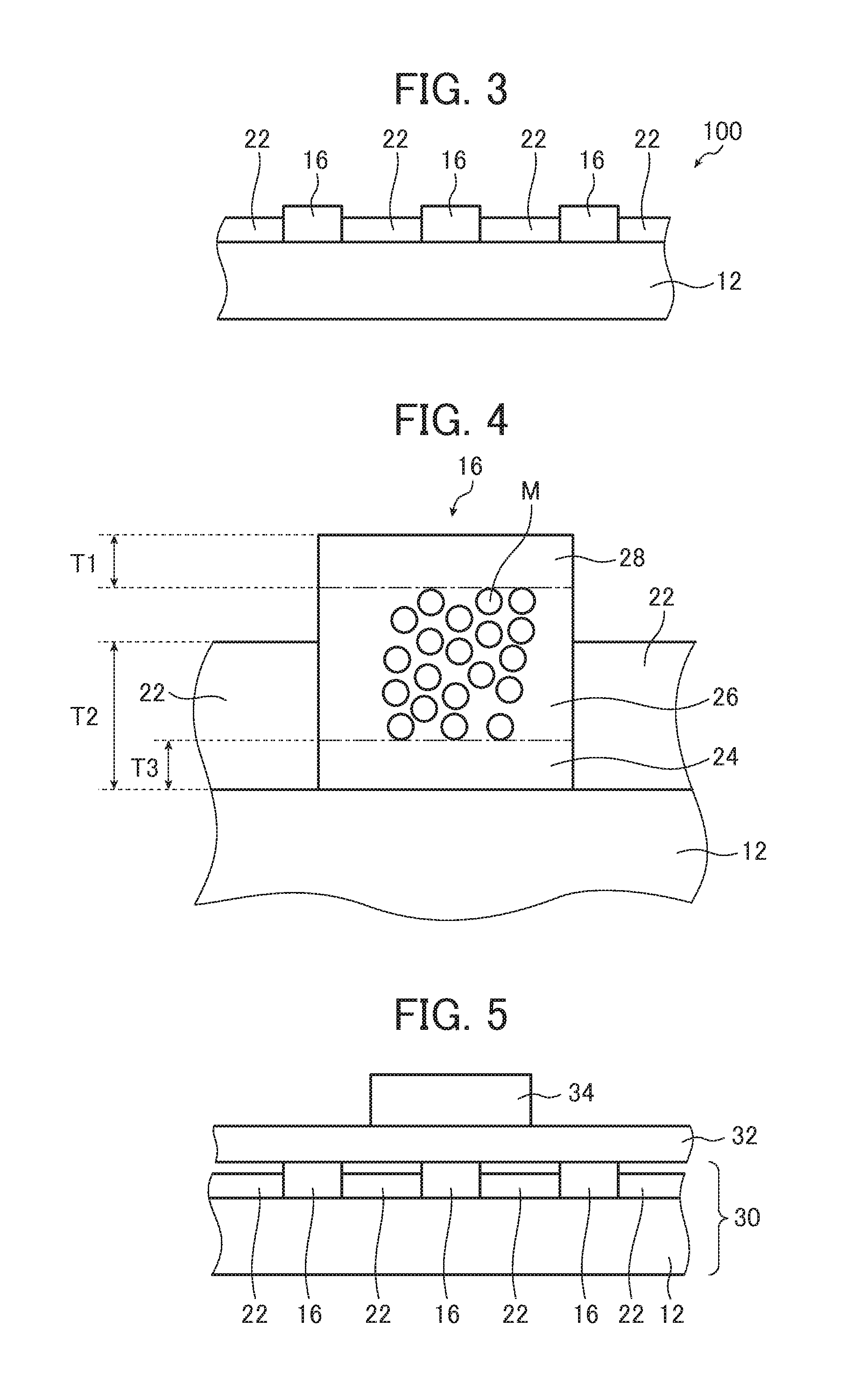
A manufacturing method of a conductive sheet includes: a step A of forming a silver halide-containing photosensitive layer, which contains silver halide, gelatin, and a polymer different from the gelatin and in which a mass ratio (Y / X) of a mass Y of the polymer to a mass X of the gelatin is equal to or greater than 0.1, on a support; a step B of forming conductive portions containing metal silver by performing exposure and then development treatment on the silver halide-containing photosensitive layer; and a step C of treating the support having the conductive portions with an oxidant which has a standard electrode potential of equal to or greater than +1.5 V and decomposes the gelatin.

Description

CROSS-REFERENCE TO RELATED APPLICATIONS[0001]This application is a Continuation of PCT International Application No. PCT / JP2013 / 080402 filed on Nov. 11, 2013, which claims priority under 35 U.S.C. §119(a) to Japanese Patent Application No. 2012-248249 filed on Nov. 12, 2012 and Japanese Patent Application No. 2013-121727 filed on Jun. 10, 2013. Each of the above application(s) is hereby expressly incorporated by reference, in its entirety, into the present application.BACKGROUND OF THE INVENTION[0002]The present invention relates to a manufacturing method of a conductive sheet. Particularly, the present invention relates to a manufacturing method of a conductive sheet that includes a step of decomposing and removing gelatin by using an oxidant having a predetermined standard electrode potential.[0003]Furthermore, the present invention also relates to a conductive sheet.[0004]A conductive sheet, in which thin conductive wires have been formed on a support, is widely used in a transpa...

Claims


Application Information

Patent Timeline
Patent Type & Authority Applications(United States)
IPC IPC(8): G03F7/004G03F7/16G03F7/40G03F7/20
CPCG03F7/0043G03F7/40G03F7/168G03F7/20G03C1/047G03C1/053G03C1/85G03C1/915G03C5/04G03C2001/0478G03C2001/0475H05K1/092H05K3/105H05K2201/0215H05K3/28H05K3/381H05K3/386H05K2201/0769H05K2203/0796H05K2203/162G06F2203/04103G06F3/0443G06F3/04164G06F3/041H05K3/106
Inventor TOKUNAGA, TSUKASATAJIRI, SHINSUTOU, MAKOTOFUJII, TOSHINARINAKAHIRA, SHINICHIKATAGIRI, KENSUKETONOIKE, NOZOMU
Owner FUJIFILM CORP
Learn More