Optical Gas Analyzer

a gas analyzer and optical technology, applied in material analysis, radiation pyrometry, instruments, etc., can solve the problems of high energy consumption, large dimensions, and high energy consumption, and achieve the effects of reducing energy consumption, high detectability, and fast respons

Active Publication Date: 2015-08-27
MAKSYUTENKO MICHAIL A +3
View PDF1 Cites 14 Cited by
  • Summary
  • Abstract
  • Description
  • Claims
  • Application Information

AI Technical Summary

Benefits of technology

[0041]The main advantage of the analyzer when using a photovoltaic detector is a combination of high detectability with fast response. To reduce energy consumption, the infrared radiation source selected operates in a mode of short powerful pulses thus requiring a fast detector capable to catch these pulses. Moreover, the source on/off duty rate matches, via the control unit, the same of the differential detector.
[0042]In an embodiment of the optical gas analyzer, the optical gas cell, that facilitates concentration of the infrared radiation passing therethrough, is formed of flat mirrors and spherical or parabolic mirrors, the number of the latters exceeding the number of flat ones. In this case, the infrared radiation source is directed towards the first spherical mirror which is placed at the corresponding angle to the main optical axis of the gas cell. The latter is adapted to transmit the radiation energy by the zigzag-like trajectory with multiple radiation concentration between the mirrors. Thus, an image of the source is created upon the flat mirrors and on the receiving device, where the filter mirror is installed at an angle of 45 degrees to normal lines of the measuring and the reference photovoltaic detectors located at 90° to each other. According to the subject matter, the efficient use of the multi-path mirrored optical cell is possible if a pulse light-emitting diode is used as the infrared radiation source. In this case, the differential receiving device is located so that the radiation source image plane at the outlet of the cell coincides with the plane of th

Problems solved by technology

high energy consumption due to the loss of a substantial energy portion of the IR radiation source at the mirror reflector and due to the IR radiation flow interruption by the disc with a profile window, because only small areas within the wide spectrum of the IR radiation of the source are used;
The disadvantages of this analyzer include large dimensions and high energy consumption.
The cell fails to protect against temperature external conditions.
However, the use of the photovoltaic detector in the known gas analyzer does not provide a balance of high detectability and fast response.
The disadvantage of the known device is the use of the immersion diodes, which possess uncontrollable axis misalignment of optical scheme and diagrams.
The use of immersion diodes results in the complication of the gas analyzer design due to having to add adjusting devices, and in the increase in dimensions.
When using such matrix, however, it is impossible to facilitate a simultaneous beaming concentration on a single photodetector for each light-emitting diode within the matrix and, at the same time, to minimize optical unit

Method used


Image

  • Optical Gas Analyzer
  • Optical Gas Analyzer
  • Optical Gas Analyzer

Examples


Embodiment Construction

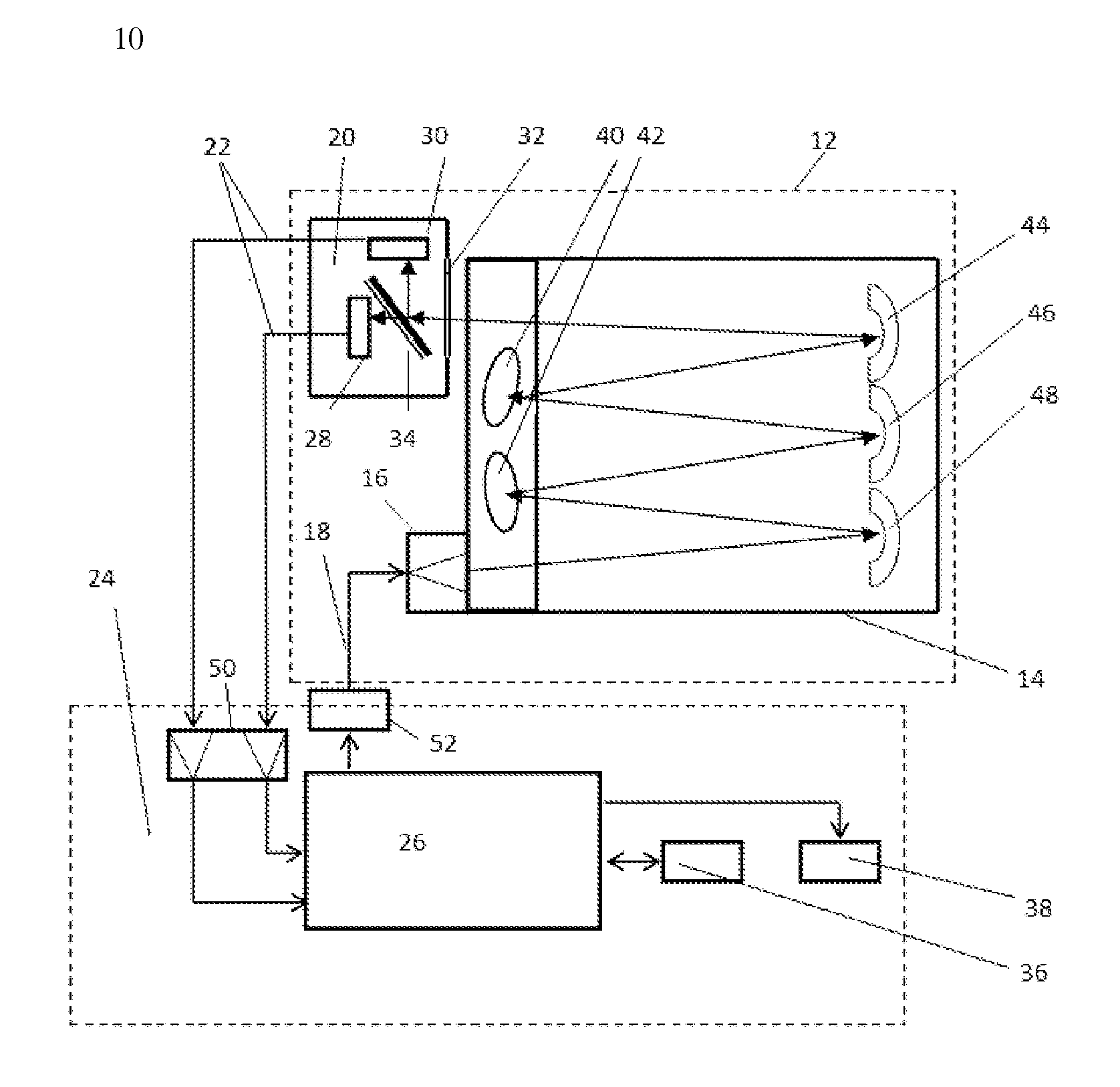
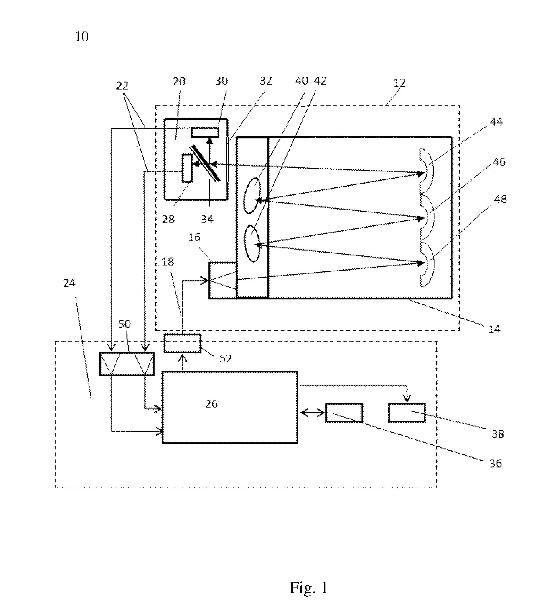
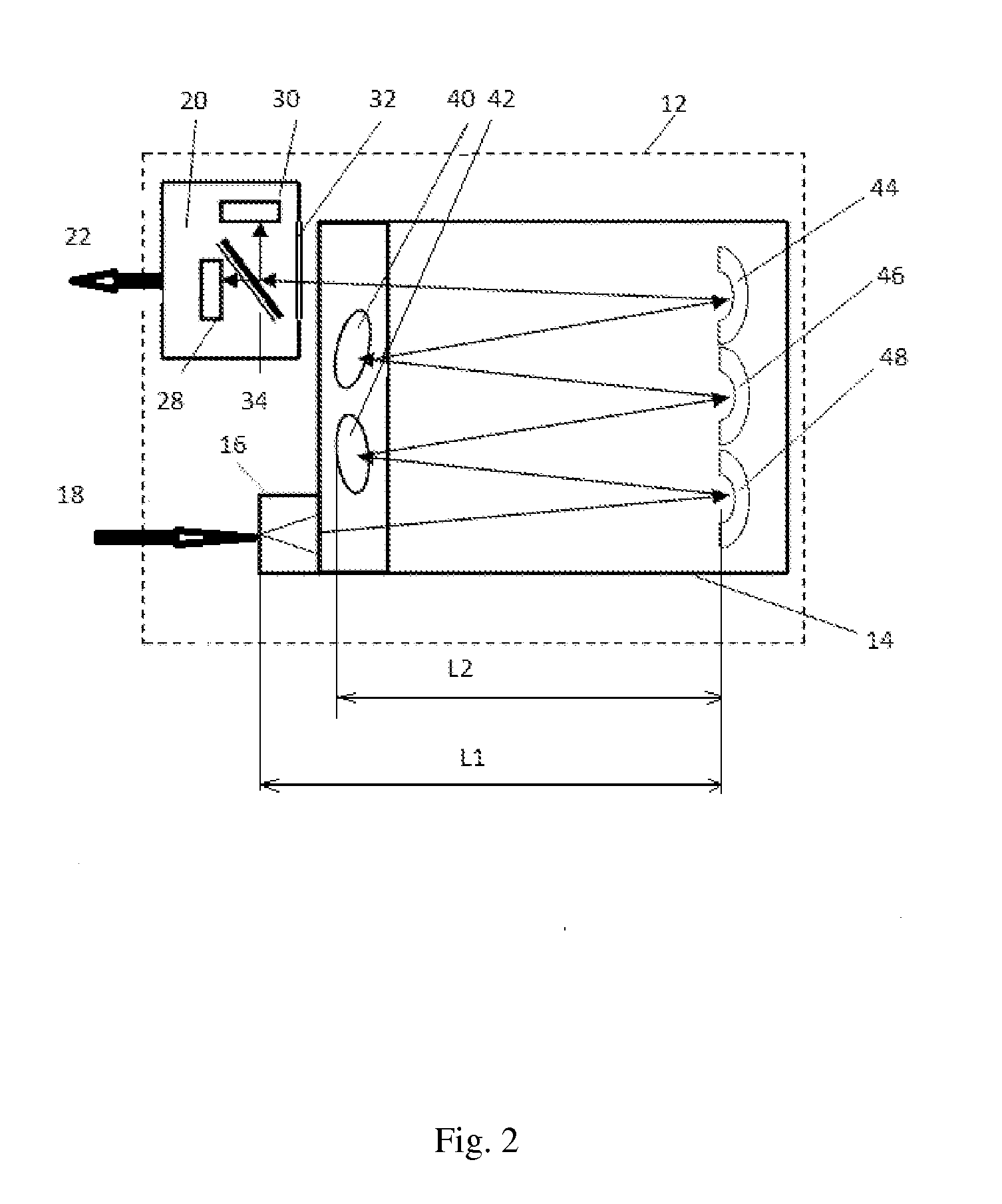
[0054]The feasibility of the optical gas analyzer is explained in the following description. The present optical gas analyzer 10 (FIG. 1) comprises an optical unit 12 with an optical gas cell 14 providing for the infrared radiation passage, an infrared radiation source 16 located at the inlet 18 of the optical unit 12, immediately before the gas cell 14, and also a detector 20 of the infrared radiation located at the outlet 22 of the optical unit 12, immediately after of the above-mentioned cell 14. There is also a control unit 24 comprising a microcontroller 26, coupled with the infrared radiation source 16 and the infrared radiation detector 20. The control unit 24 is adapted to change operation modes of the infrared radiation source 16, and to process the infrared radiation, received by the detector 20, to display the results obtained. The optical gas cell 14 is adapted to transmit radiation energy along the zigzag-like trajectory with multiple radiation concentration from its in...


PUM


Abstract

An optical gas analyzer, preferably for hydrocarbons, comprises an optical gas cell, an infrared LED pulse radiation source and a radiation detector at the inlet and outlet of the cell, respectively, and a control unit. The detector comprises measuring and reference photovoltaic detectors, a filter window at the detector inlet, and a filter mirror inside the same. Resulting spectral transmission and reflection characteristics of the filter window and filter mirror match the absorption spectrum for the gas and the radiation spectrum of the source. The filter window and filter mirror compensate external influence upon the radiation path trajectory within the cell on the gas concentration result.
The cell comprises spherical or parabolic and flat mirrors arranged in a checker order to transmit the beam of the source via a zigzag-like trajectory between the mirrors.
The analyzer offers a fast response and high sensitivity along with minimized power consumption and dimensions.

Description

CROSS-REFERENCE TO RELATED APPLICATIONS[0001]This application is a continuation-in-part of U.S. application Ser. No. 13 / 885,097 filed May 13, 2013, which is a National phase application of PCT / RU2011 / 000894 filed Nov. 11, 2011, claiming priority to Russian application RU2010147341 filed Nov. 12, 2010, all three applications being hereby incorporated by reference in their entirety.TECHNICAL FIELD[0002]The following description generally relates to the field of measurement technique, and more specifically to devices for controlling the content of hydrocarbons in the atmosphere. These devices represent measuring apparatuses, mostly portable, configured to continuously control the level of explosive concentrations of, for example, methane within industrial premises or mines, by means of measuring and analyzing the gas, incoming into the device from environment, via molecular diffusion, i.e. without creating a positive gas flow.TECHNICAL BACKGROUND[0003]Known has been an infrared absorpt...

Claims


Application Information

Patent Timeline
IPC IPC(8): G01N21/3504G01N21/25
CPCG01N21/3504G01N21/255G01N2201/0636G01N2201/068G01N2201/061G01N21/031
Inventor MAKSYUTENKO, MICHAIL A.NEPOMNYASHCHY, SERGEY V.POGODINA, SOFIA B.KHREBTOV, VYACHESLAV V.
Owner MAKSYUTENKO MICHAIL A
Why Eureka
Try Eureka