

Laminated glazing with coloured reflection and high solar transmittance suitable for solar energy systems
a technology of solar energy system and laminated glazing, which is applied in the field of laminated glazing with coloured reflection and high solar transmittance, can solve the problems of limiting the possibilities of solar roll glass, extra-white float glass (very low iron-content), or polymeric materials, and the surface flatness is also critical, so as to improve the flatness, improve the appearance of tiles, and reinforce the masking effect of coloured filter
Inactive Publication Date: 2015-09-03
SWISSINSO HLDG INC
View PDF7 Cites 23 Cited by
- Summary
- Abstract
- Description
- Claims
- Application Information
AI Technical Summary
Benefits of technology
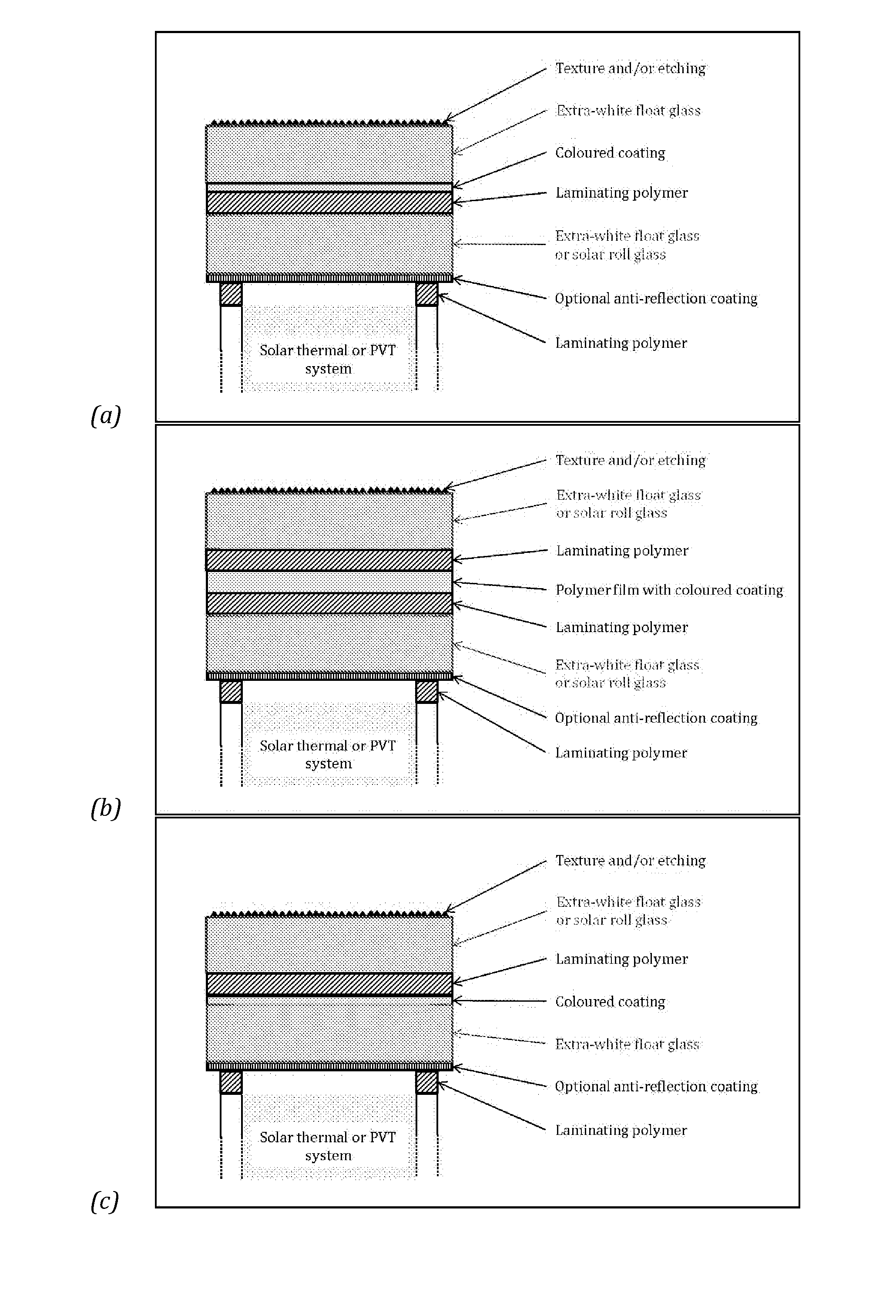
The present invention is a solar glazing unit with enhanced masking effect, angular colour stability, and good mechanical strength. It consists of coloured laminated glazing made of glass with a high-speed coating process using other oxides. The thick SiO2 coatings are replaced by other oxides for faster deposition. An etching treatment is applied to create diffuse light transmittance and reinforce the masking effect. The glass panes and other elements are joined together by lamination using high-solar transmittance polymers. The lamination process offers flexibility and is combined with a security treatment for facade applications. The coloured coating is encapsulated to avoid any colour change due to water condensation on the inner side of the glazing.
Problems solved by technology
In order to ensure a maximal efficiency of the solar energy system, the substrate has to present a high solar transmittance, thus limiting the possibilities to solar roll glass, extra-white float glass (very low iron-content) or polymeric materials such as polyethylene terephthalate (PET), polyethylene naphtalate (PEN), fluorocarbon polymer (PFA, FEP, ETFE, PTFE .
The surface flatness is also a critical issue, especially for facade applications.
Method used
View moreImage
Smart ImageViewing Examples

Examples
example 1
[0148]air / / 136 nm of L / 222 nm of H / / glass / / 222 nm of H / 136 nm of L / / air with nH=1.54 and nL=1.8
example 2
[0149]air / / glass / / 30 nm of H / 25 nm of L / 320 nm of H / / polymer with nH=2.4 and nL=1.65
example 3
[0150]air / / glass / / 185±12 nm of H / 25±12 nm of L / 35±12 nm of H / 35±12 nm of L / 130±12 nm of H / / polymer with nH =2.4 and ni, =2.0
Login to View More PUM
| Property | Measurement | Unit |
|---|---|---|
| visible reflectance | aaaaa | aaaaa |
| total hemispherical solar transmittance | aaaaa | aaaaa |
| solar transmittance | aaaaa | aaaaa |
Abstract
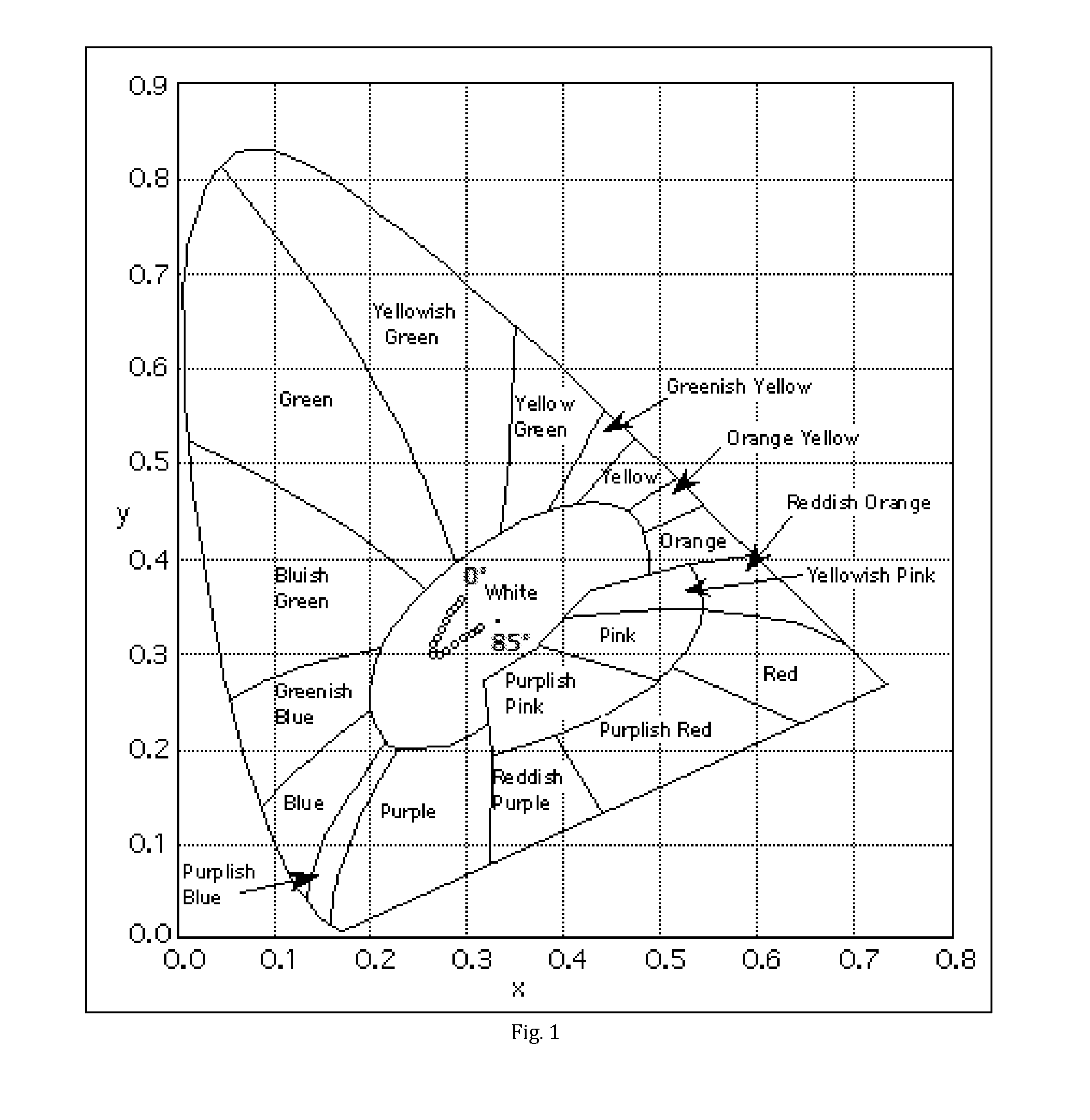
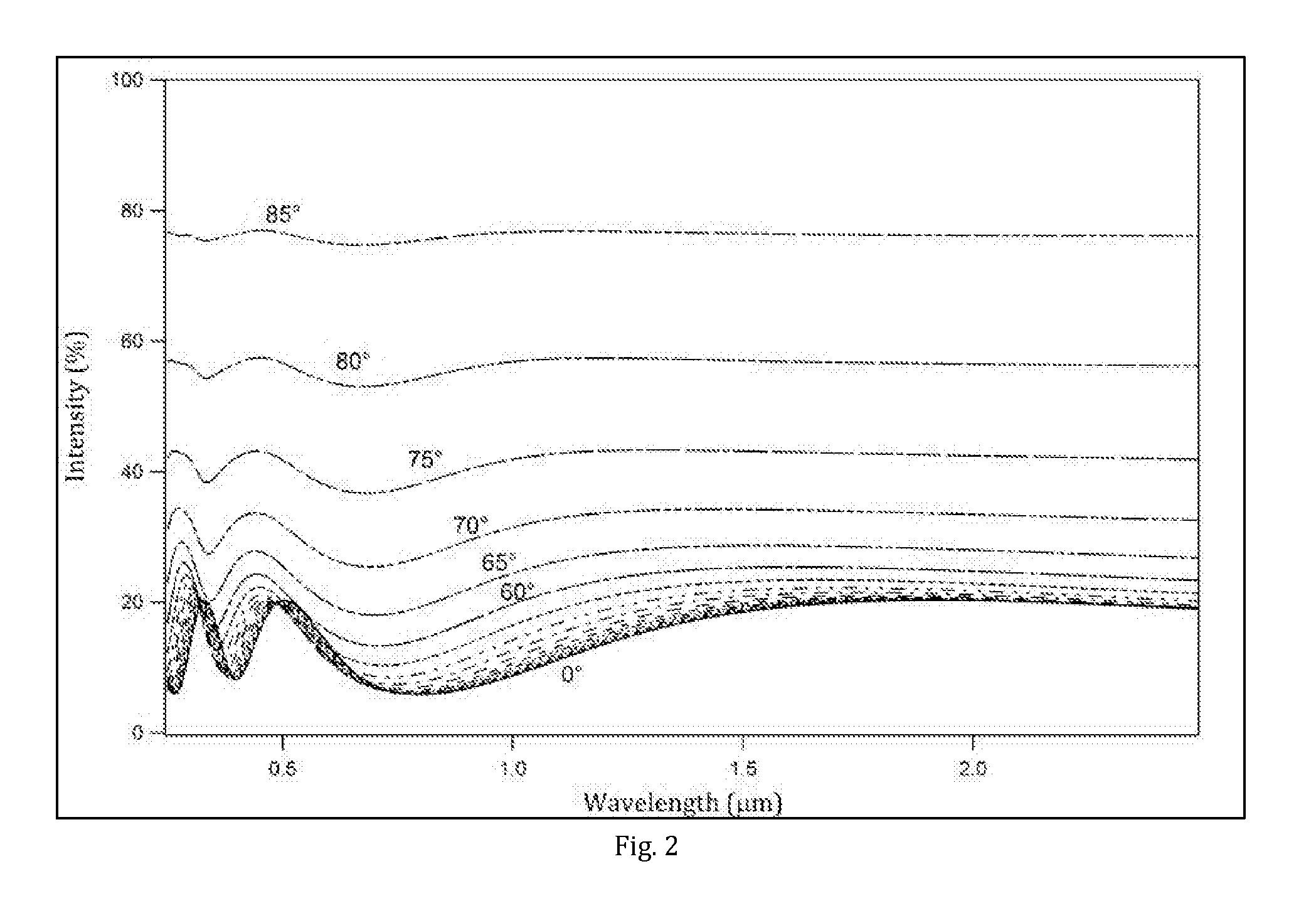
Laminated and etched glazing unit for architectural integration of solar energy systems comprising a substrate delimited by two main faces and a multi-layered interference filter also delimited by two main faces, one main face of said substrate being adapted to be in contact with an incident medium, the other main face being in contact with a main face of said interference filter, the other main face of said interference filter being adapted to be in contact with an exit medium; said incident medium having a refractive index ninc=1, said substrate having a refractive index nsubstrate defined as follows: 1.45≦nsubstrate≦1.6 at 550 nm, and said exit medium being defined as follows 1.45≦nexit≦1.6 at 550 nm; and wherein said unit is designed in such a way that the following requirements are met: 1a) The saturation of the colour, given by C*ab=√(a*)2+(b*)2, according to the CIE colour coordinates L*, a* and b* under daylight illumination CIE-D65 is higher than 8 at near-normal angle of reflection, except for grey and brown. 1b) The visible reflectance at near-normal angle of reflection Rvis is higher than 4%. 1c) The variation of the dominant wavelength λMD of the dominant colour MD of the reflection with varying angle of reflection Θr is smaller than 15 nm for Θr<60°. 1d) The total hemispherical solar transmittance at near-normal incidence is above 80%.
Description
FIELD OF THE INVENTION[0001]The invention deals with coloured laminated glazing suitable for solar energy systems offering architectural integration of solar energy systems, e.g. as solar active glass facades.DEFINITIONS[0002]Direct Transmittance[0003]If parallel beams of radiation incident on a surface, an interface, or a specimen result in transmitted parallel beams, the transmittance is considered as direct. This is the case e.g., for flat surfaces or interfaces.[0004]Diffuse Transmittance[0005]If parallel beams of radiation incident on a surface, an interface, or a specimen result in a more or less wide angular distribution of transmitted beams, the transmittance is considered as diffuse. This is the case e.g., for rough surfaces or interfaces, or for specimens of granular structure.[0006]In general, the diffuse transmittance depends on the angle of incidence and the wavelength X of the radiation. If the angle of incidence is not explicitly mentioned, commonly normal incidence i...
Claims
Login to View More Application Information
Patent Timeline
 Patent Type & AuthorityApplications(United States)
IPC IPC(8): H02S20/26H02S20/23H01L31/048B32B7/02B32B17/06
CPCH02S20/26B32B7/02B32B17/064B32B2457/00H02S20/23B32B2307/418H01L31/0488B32B17/10036B32B17/10146B32B17/10201B32B17/10743B32B17/10761B32B17/10788Y02E10/40F24S80/52Y10T428/24355Y10T428/24942B32B17/1011Y02E10/50Y02B10/10B32B17/10005B32B2367/00G02B5/281G02B5/286Y10T428/2495Y10T428/24967B32B17/06
InventorHODY LE CAER, VIRGINIESCHULER, ANDREAS
OwnerSWISSINSO HLDG INC