Wireless power transmission system

a power transmission system and wireless technology, applied in the direction of transformers, inductances, transportation and packaging, etc., can solve the problems of reducing the size of the apparatus, reducing the power transmission efficiency, etc., and achieve the effect of improving power transmission efficiency and suppressing the variation of output voltag

Inactive Publication Date: 2015-09-03
MURATA MFG CO LTD
View PDF4 Cites 18 Cited by
  • Summary
  • Abstract
  • Description
  • Claims
  • Application Information

AI Technical Summary

Benefits of technology

[0019]According to the present invention, compared with the case of existing resistance load modulation, it is possible to suppress variations in an output voltage and improve power transmission efficiency.

Problems solved by technology

In addition, since coils are used, it is difficult to reduce the sizes of the apparatuses.
However, in both a magnetic-field-coupling system and an electric-field-coupling system, when an AC voltage or the like is modulated, if simple load modulation using a resistance load is performed, an output voltage varies due to the modulation operation and, hence, it is necessary to interrupt power transmission while transmitting data from the power receiving apparatus to the power transmitting apparatus.
In addition, power is consumed by a modulation unit, thereby causing a decrease in power transmission efficiency.

Method used


Image

  • Wireless power transmission system
  • Wireless power transmission system
  • Wireless power transmission system

Examples


first embodiment

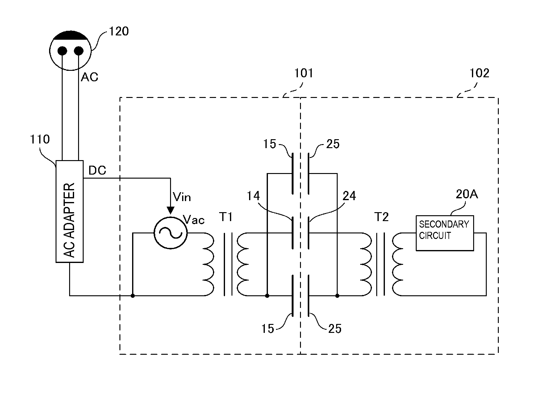
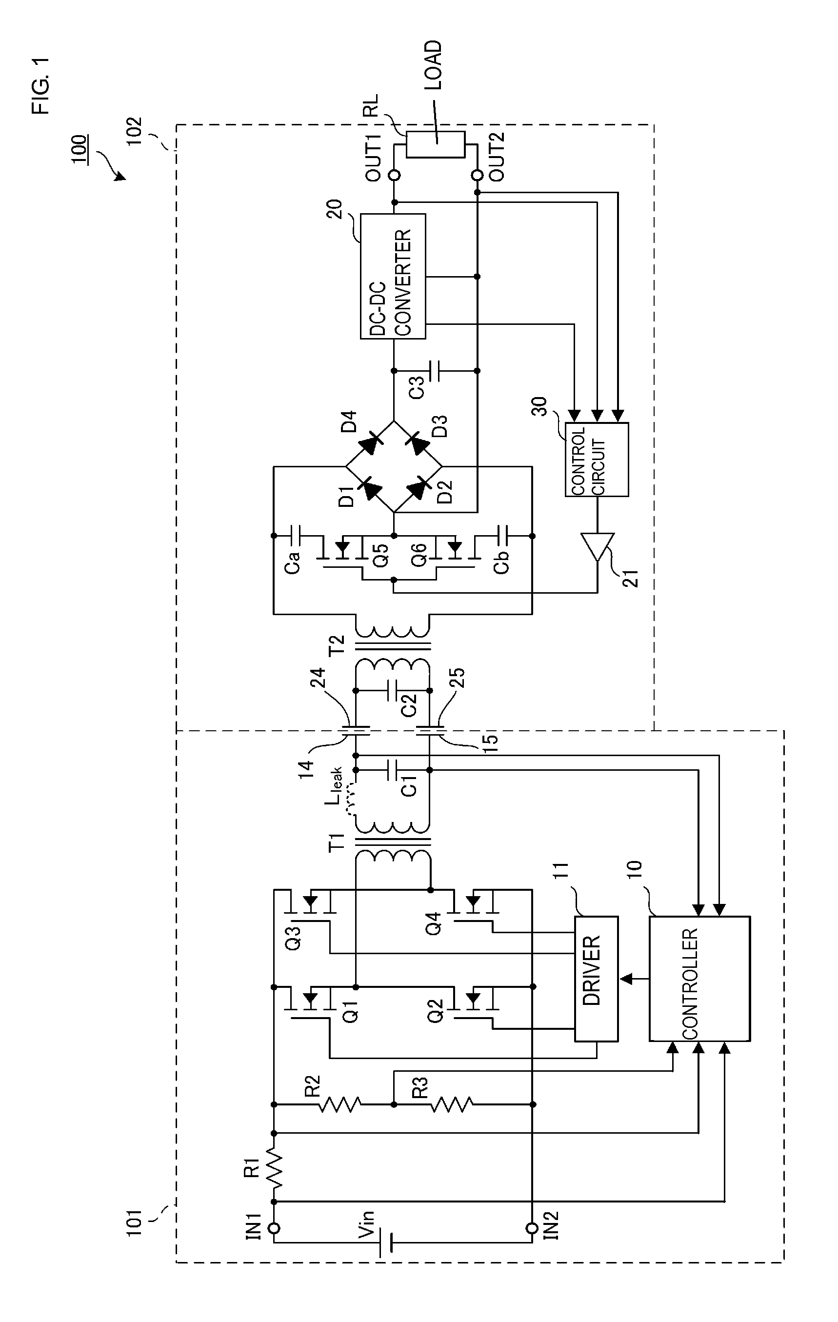
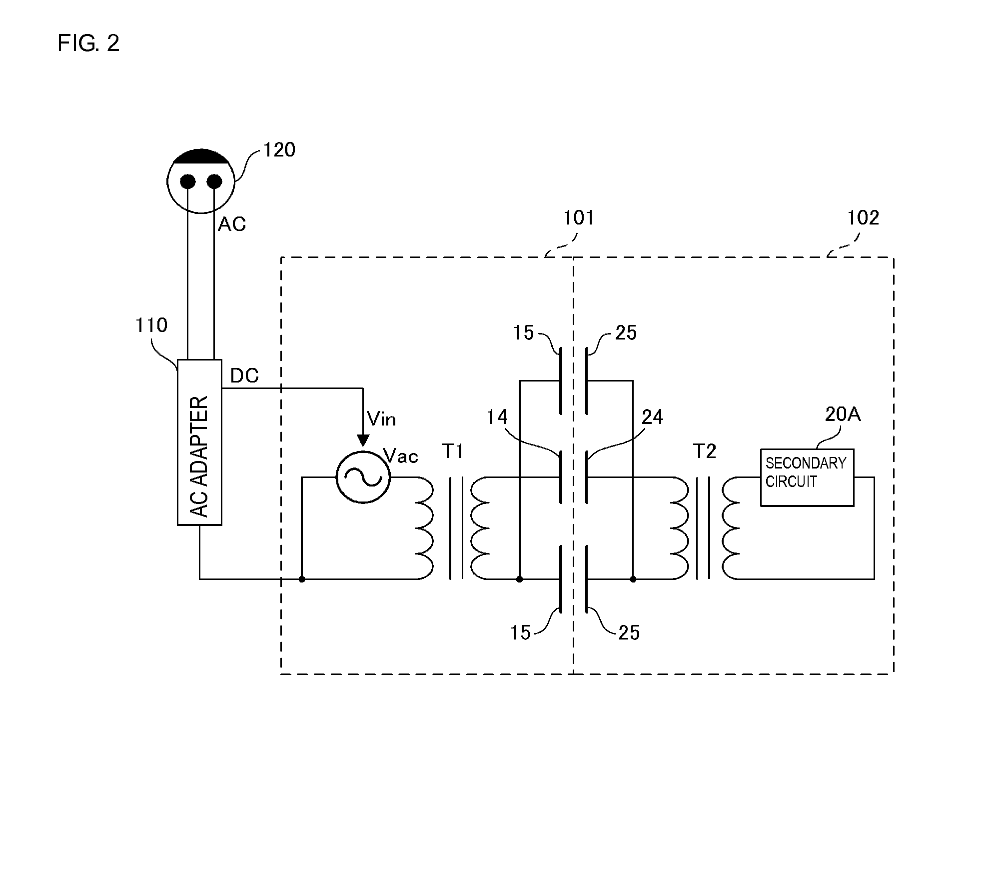
[0032]FIG. 1 is a circuit diagram of a wireless power transmission system according to a first embodiment. FIG. 2 is a schematic diagram of the wireless power transmission system.

[0033]A wireless power transmission system 100 according to the present embodiment is formed of a power transmitting apparatus 101 and a power receiving apparatus 102. The power receiving apparatus 102 includes a load RL. The load RL is a secondary battery. The power receiving apparatus 102 is, for example, a mobile electronic apparatus including the secondary battery. Examples of the mobile electronic apparatus include a cellular phone, a personal digital assistant (PDA), a mobile music player, a notebook computer, and a digital camera. The power receiving apparatus 102 is mounted on the power transmitting apparatus 101, which is a charging stand for charging the secondary battery of the power receiving apparatus 102.

[0034]The power transmitting apparatus 101 is connected to a power supply 120 through an A...

second embodiment

[0058]FIG. 8 is a circuit diagram of a wireless power transmission system according to a second embodiment. FIG. 9 is a schematic diagram of a wireless power transmission system. The wireless power transmission system 100 according to the first embodiment transmits power using electric field coupling. However, a wireless power transmission system 100A according to the second embodiment transmits power using magnetic field coupling.

[0059]In a power transmitting apparatus 101A, a power transmitting side coupling coil (power transmitting side coil of the present invention) 16 is connected to the secondary coil of the step-up transformer T1. The power transmitting side coupling coil 16 and the capacitor C1 form a series resonant circuit. In a power receiving apparatus 102A, a power receiving side coupling coil (power receiving side coil of the present invention) 26, in which a high-frequency current is induced due to electromagnetic induction between the power receiving side coupling co...

third embodiment

[0064]FIG. 11 is a circuit diagram of a wireless power transmission system according to a third embodiment. The power transmitting apparatus 101 provided in a wireless power transmission system 100C according to the third embodiment is similar to that of the first embodiment. A power receiving apparatus 102C has a configuration in which a series circuit formed of a switching device Q7 and a capacitor Cc and a series circuit formed of a switching device Q8 and a capacitor Cd are respectively connected in parallel with the diodes D2 and D4 of the power receiving apparatus 102 according to the first embodiment. In the third embodiment, four-level (four-value) data can be transmitted from the power receiving apparatus to the power transmitting apparatus, thereby enabling high-rate information transmission, whereas binary data is transmitted in the first and second embodiments.

[0065]A series circuit formed of the switching device Q7 and the capacitor Cc and a series circuit formed of the...


PUM


Abstract

A wireless power transmission system in which power is transmitted from a power transmitting apparatus to a power receiving apparatus that includes: a diode bridge formed of first and second diodes whose anodes are connected to each other, and third and fourth diodes whose cathodes are connected to each other; series circuits formed of semiconductor switching devices and capacitors respectively connected in parallel with the first and second diodes, and a control circuit that inputs a modulation signal to the gates of the semiconductor switching devices. The power transmitting apparatus includes a controller that reads the modulation signal on a basis of a change in a DC current input at an input terminal. The a wireless power transmission system can transmit data from the power receiving apparatus to the power transmitting apparatus without interrupting power transmission, reducing output voltage variations, and suppressing degradation of power transmission characteristics.

Description

CROSS REFERENCE TO RELATED APPLICATIONS[0001]The present application is a continuation of PCT / JP2013 / 073610 filed Sep. 3, 2013, which claims priority to Japanese Patent Application No. 2012-284725, filed Dec. 27, 2012, the entire contents of each of which are incorporated herein by reference.FIELD OF THE INVENTION[0002]The present invention relates to wireless power transmission systems that enable data communication from a power receiving apparatus to a power transmitting apparatus.BACKGROUND OF THE INVENTION[0003]Examples of typical known wireless power transmission systems include magnetic-field-coupling power transmission systems in which power is transmitted from the primary coil of a power transmitting apparatus to the secondary coil of a power receiving apparatus using a magnetic field. However, in this system, when power is transmitted using magnetic field coupling, since electromotive force is strongly influenced by the magnitude of magnetic flux passing through each coil, ...

Claims


Application Information

Patent Timeline
Patent Type & Authority Applications(United States)
IPC IPC(8): H04B5/00H02J7/00H02J7/02H02J5/00
CPCH04B5/0037H02J7/025H02J7/007H02J5/005H02J50/05H02J7/00712H02J50/12
Inventor ICHIKAWA, KEIICHISAKAI, HIRONORI
Owner MURATA MFG CO LTD
Why Eureka
Try Eureka