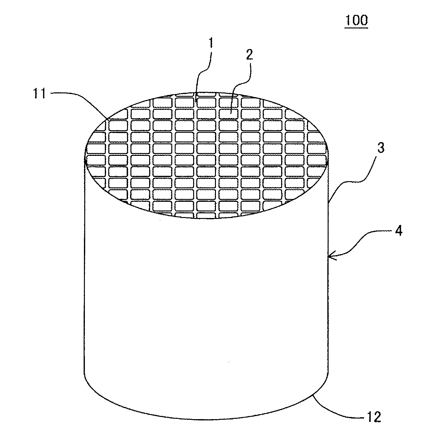
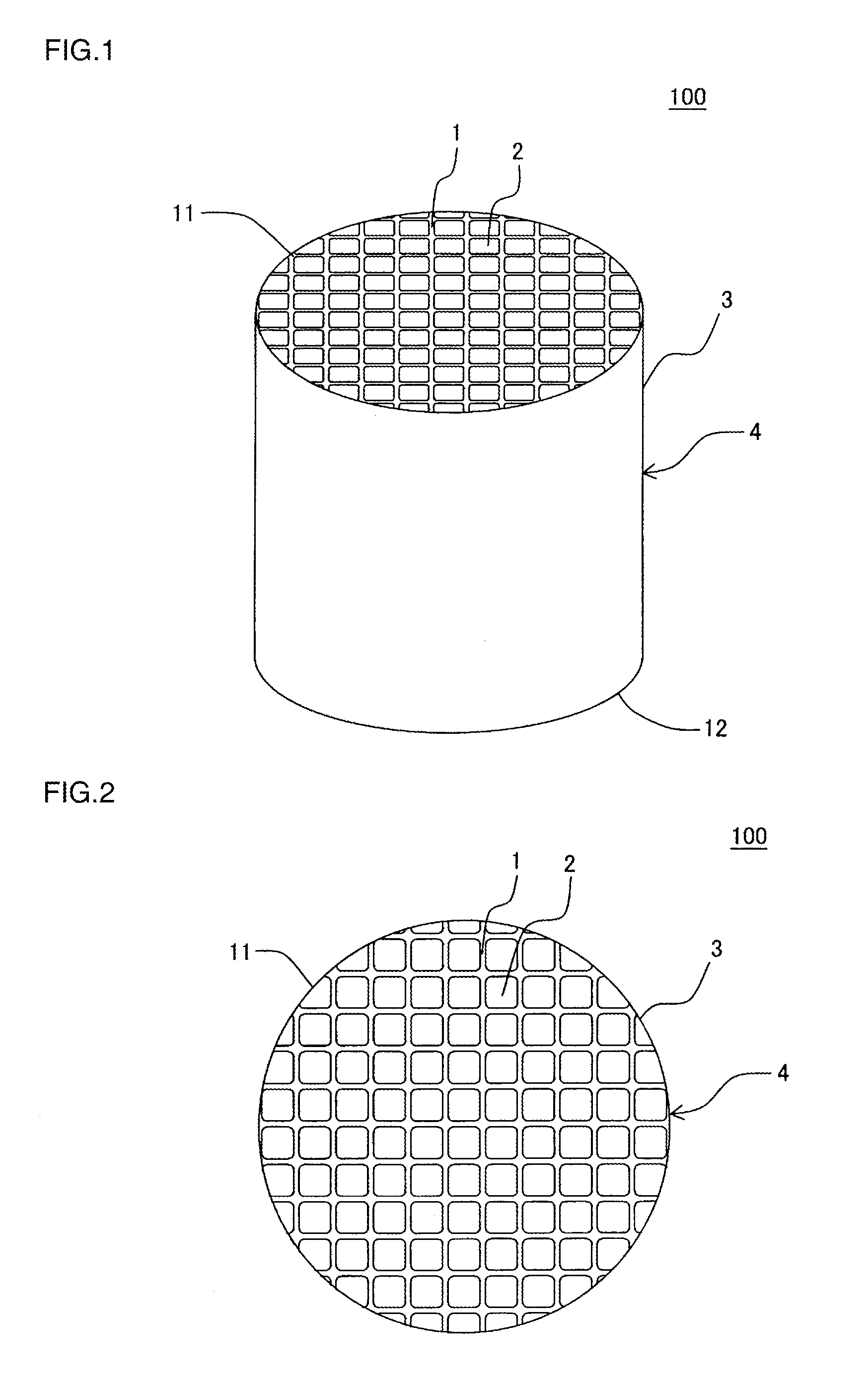
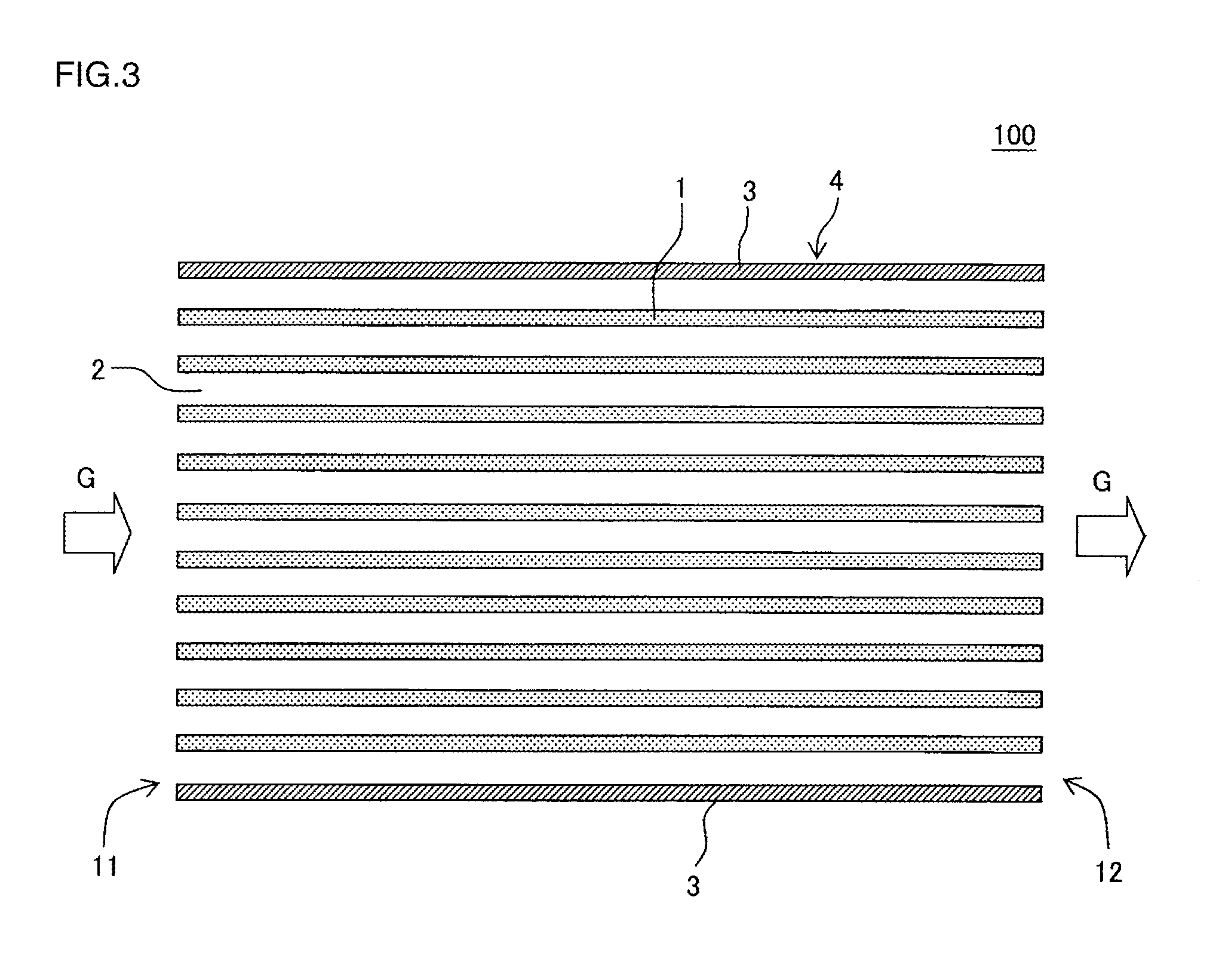
Honeycomb structure

a honeycomb and structure technology, applied in the field of honeycomb structure, can solve the problems of insufficient effect and limited improvement on wettability, and achieve the effects of less likely to be damaged, high thermal conductivity of this porous body, and high strength of the porous body

Active Publication Date: 2015-09-17
NGK INSULATORS LTD
View PDF0 Cites 9 Cited by
  • Summary
  • Abstract
  • Description
  • Claims
  • Application Information

AI Technical Summary

Benefits of technology

[0022]The honeycomb structure of present invention includes a honeycomb structure body that has a partition wall. The partition wall is constituted of the porous bodies. The porous body includes the refractory aggregate and the bonding material. The main constituent of the bonding material is the oxide material. The bonding material bonds the refractory aggregates. In the honeycomb structure of the present invention, in the observation of the cross section of the partition wall with the electron microscope, when observing any given ten visual fields meeting the condition (1), the number of refractory aggregates meeting the condition (2) is five pieces or more in all of these ten visual fields. The honeycomb structure of the present invention features high strength of the porous bodies, which constitute the partition wall, and also high thermal conductivity of this porous body. Further, the honeycomb structure also provides an effect of being less likely to be damaged in usage under high temperature environment. That is, according to the present invention, the bond neck portion, in which the refractory aggregates are bonded to each other by the bonding material, thickens. This improves the strength of the porous bodies constituting the partition wall. The honeycomb structure of the present invention also provides an effect of low pressure loss. That is, the number of refractory aggregates meeting the condition (2) is five pieces or more. Accordingly, a pore formed in the porous bodies, which constitute the partition wall, likely to be a communication hole communicating from one surface to the other surface of this partition wall. This reduces both of an initial pressure loss and pressure loss when PM deposits. The initial pressure loss is pressure loss after coating a catalyst for purifying exhaust gas to the partition wall of the honeycomb structure. The pressure loss when PM deposits is pressure loss when PM, such as soot, deposits on a surface of the partition wall.

Problems solved by technology

However, the improvement on wettability is limited to a material that bonds the silicon carbide with the metallic silicon.
This also has a problem of failing to obtain sufficient effect actually.

Method used


Image

  • Honeycomb structure
  • Honeycomb structure
  • Honeycomb structure

Examples


example 1

[0091]Example 1 first prepared a forming raw material for fabricating a honeycomb structure by the following method. Silicon carbide (SiC) powder, which becomes the refractory aggregate, and raw material powder for generating bonding material were mixed at a ratio of 70:30 (volume ratio). Thus, “mixed powder” was fabricated. The silicon carbide (SiC) powder had the average particle diameter of 14 μm and the specific surface area of 4000 cm2 / cm3. As the silicon carbide (SiC) powder, which becomes the refractory aggregate, the mixture of the powders with two kinds of average particle diameters classified by the sieving was used. The silicon carbide powders of two kinds of average particle diameters were powder classified with the JIS standard sieve with meshes of #800 or more and powder classified with the JIS standard sieve with meshes of #1000 or more. As the powder for generating bonding material, powder that contains talc of 45.1 volume %, kaolin of 32.8 volume %, and aluminum hyd...

examples 2 and 3

[0107]In Examples 2 and 3, the aggregate raw material average particle diameter (μm), the content ratio of Na2O (%), and the aggregate raw material specific surface area (cm2 / cm3) were changed as shown in Table 1. Except for that, the honeycomb structure was manufactured by the method similar to Example 1. Example 2 used the silicon carbide (SiC) powder of the average particle diameter of 13 μm as the refractory aggregate. Example 3 used the silicon carbide (SiC) powder of the average particle diameter of 11.5 μm as the refractory aggregate. Table 1 shows the aggregate main constituent, the bonding material main constituent, the bonding material proportion (%), the aggregate raw material average particle diameter (μm), the sintering aid, and the content ratio of Na2O (%) in Examples 2 and 3. Table 1 shows the firing temperature during manufacture (° C.), the thickness of partition wall (μm), the cell density (cell / cm2), the porosity of partition wall (%), the diameter of end face of...


PUM

PropertyMeasurementUnit
particle diameteraaaaaaaaaa
temperatureaaaaaaaaaa
mass %aaaaaaaaaa

Abstract

A honeycomb structure includes a honeycomb structure body having a partition wall which is constituted of a porous body. The porous body includes a refractory aggregate and a bonding material. The porous body constituting includes the bonding material at a mass proportion of 20 to 35 mass %. In an observation of a cross section of the partition wall with an electron microscope, when observing any given ten visual fields meeting a following condition (1), the number of refractory aggregates meeting a following condition (2) is five pieces or more in all of the ten visual fields.
Condition (1): a proportion of an area occupied by the bonding material is 30% or more.
Condition (2): the refractory aggregate has a particle diameter of 5 μm or more, and 60% or more of an outer circumference of the refractory aggregate is surrounded by the bonding material.

Description

[0001]The present application is an application based on JP 2014-049340 filed on Mar. 12, 2014 with Japan Patent Office, the entire contents of which are incorporated herein by reference.BACKGROUND OF THE INVENTION[0002]1. Field of the Invention[0003]The present invention relates to a honeycomb structure. More specifically, the present invention relates to a honeycomb structure that can be preferably used as a filter and a catalyst carrier for purifying vehicle exhaust gas.[0004]There has widely been used a porous honeycomb structure as a filter for trapping and removing a particulate matter contained in a dust-containing fluid such as a diesel engine exhaust gas or as a catalyst carrier for loading a catalyst component for purifying harmful substances in exhaust gas. In addition, it is known that refractory particles such as silicon carbide (SiC) particles are used as a constituent material for such a honeycomb structure.[0005]For example, as a catalyst carrier using the honeycomb ...

Claims


Application Information

Patent Timeline
Patent Type & Authority Applications(United States)
IPC IPC(8): C04B38/00B01D46/24B01J35/04F01N3/022B01J27/224B01J21/16
CPCC04B38/0009B01J27/224B01D46/2429B01J35/04F01N3/0222B01J21/16C04B38/0019C04B2111/00793C04B2111/0081C04B35/565C04B35/584C04B2235/3206C04B2235/3217C04B2235/3418C04B2235/3826C04B2235/3873C04B2235/5436B01D46/2418C04B35/6303C04B35/6316C04B2235/3218C04B2235/3229C04B2235/349C04B2235/5409C04B2235/5472C04B2235/786C04B2235/80C04B2235/96Y10T428/24149
Inventor ICHIKAWA, SHUICHIMIZUNO, ATSUSHIMIYAIRI, YUKIO
Owner NGK INSULATORS LTD
Why Eureka
Try Eureka