

Rare earth-cobalt permanent magnet
a permanent magnet, rare earth technology, applied in the direction of magnetic materials, basic electric elements, magnetic bodies, etc., can solve the problems that the production of permanent magnets using metal mold castings fails to obtain good magnetic properties in some cases, and achieves good magnetic properties and simple devices
- Summary
- Abstract
- Description
- Claims
- Application Information
AI Technical Summary
Benefits of technology
Problems solved by technology
Method used
Image

Examples
first embodiment
[0017]A rare earth-cobalt permanent magnet according to a first embodiment is described hereinafter.
[0018]The rare earth-cobalt permanent magnet according to the first embodiment contains 23 to 27 wt % R, 3.5 to 5 wt % Cu, 19 to 25 wt % Fe, 1.5 to 3 wt % Zr, and the remainder Co with inevitable impurities. The melting point of the rare earth-cobalt permanent magnet according to the first embodiment is about 1400° C. R is a rare earth element and at least contains Sm among rare earth elements. Examples of rare earth elements include Pr, Nd, Ce and La. Further, the rare earth-cobalt permanent magnet according to the first embodiment contains an intermetallic compound that is composed predominantly of rare earth cobalt. The intermetallic compound may be SmCo5, Sm2Co17 or the like, for example.
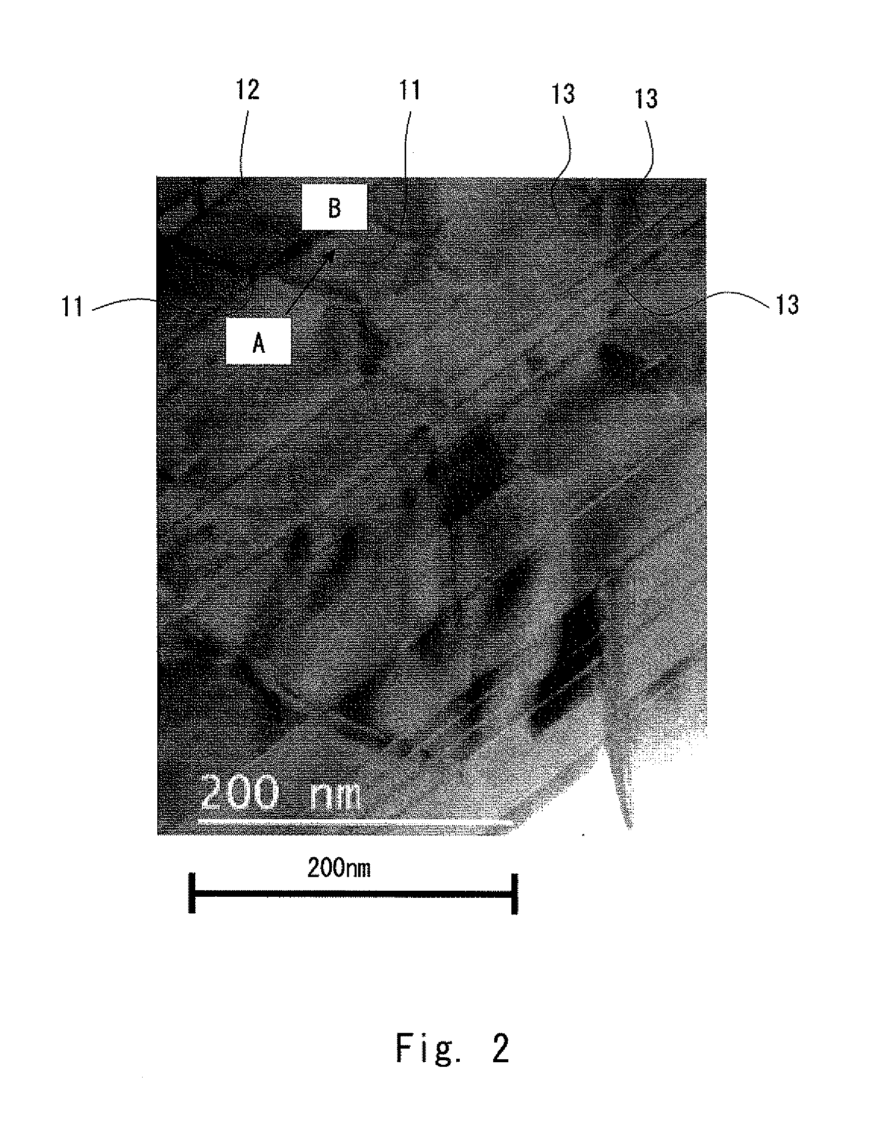
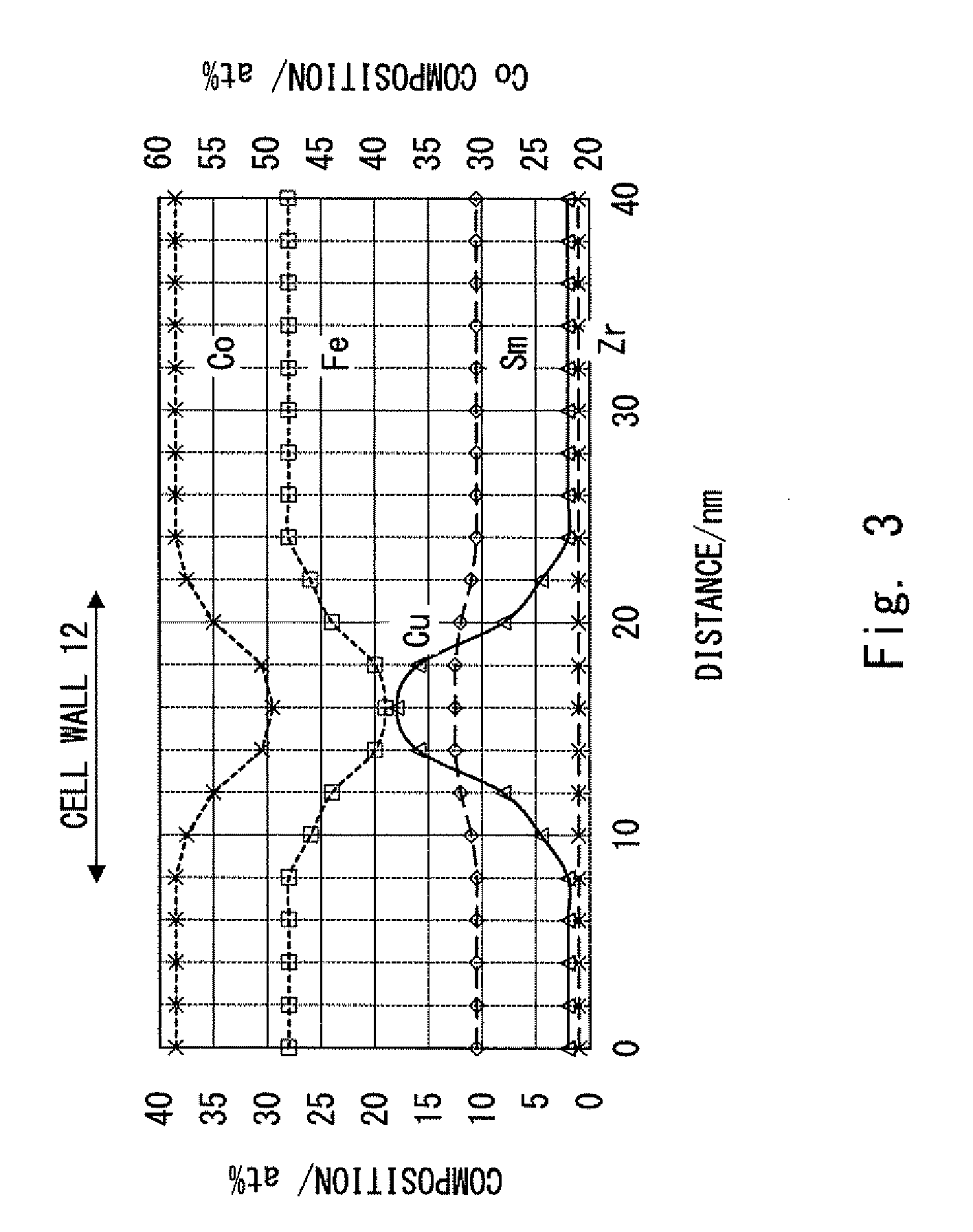
[0019]Further, the rare earth-cobalt permanent magnet according to the first embodiment has a metal structure containing crystal grains. The crystal grains have a cell phase containing Sm2Co17, a ...
experiment 1
[0032]Hereinafter, experiments conducted as examples 1 to 3 for the permanent magnet according to the first embodiment and comparative examples 1 and 2 are described with reference to Table 1 and FIGS. 2 to 5.
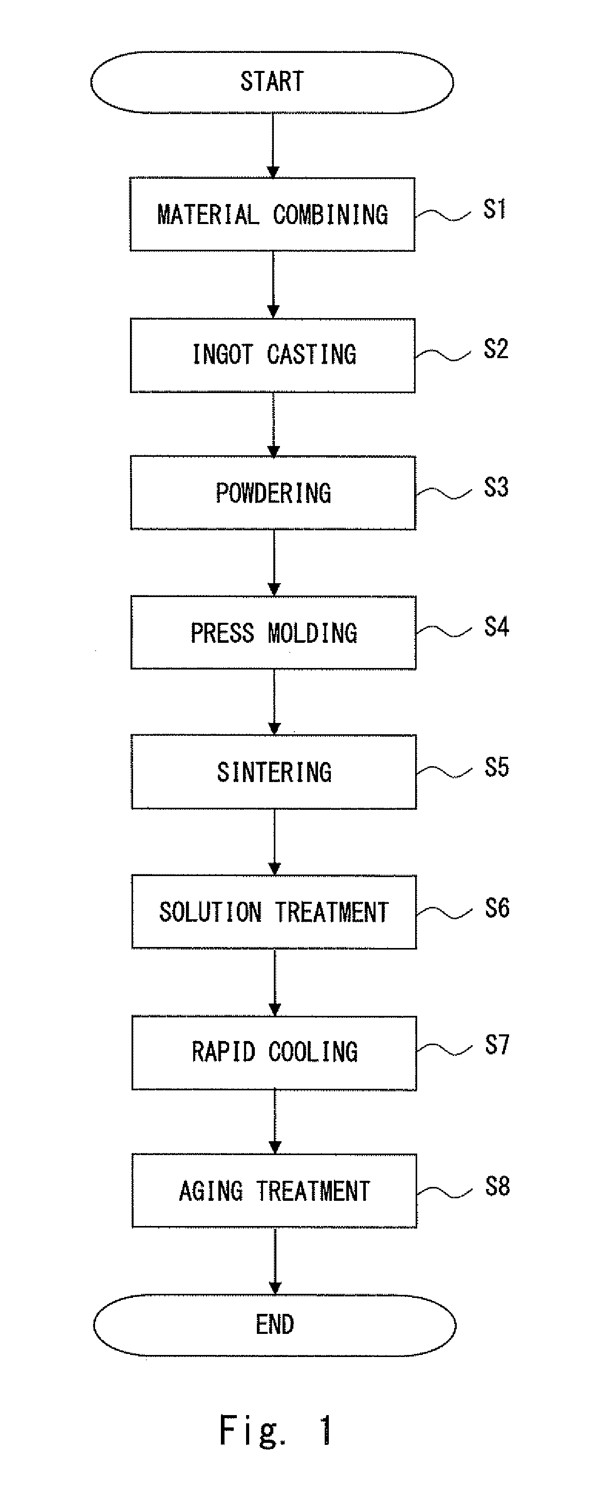
[0033]In the examples 1 to 3, a permanent magnet was produced by the same production method as described above. To be specific, in the material combining step S1, a target composition was 25.0 wt % Sm, 4.4 wt % Cu, 20.0 wt % Fe, 2.4 wt % Zr, and the remainder Co. As the master alloy containing Zr, 20% Fe-80% Zr alloy was used. Further, in the powdering step S3, an ingot was finely ground to powder with an average particle diameter (d50) of 6 μm in an inert gas atmosphere by using a jet mill In the press molding step S4, press molding was performed under the conditions of a magnetic field of 15 kOe and a press-molding pressure value of 1.0 ton / cm2. In the sintering step S5, sintering was performed at a sintering temperature of 1200° C. In the solution treatment step S6, the temp...
experiment 2
[0045]Hereinafter, experiments conducted as examples 4 to 15 for the permanent magnet according to the first embodiment and comparative examples 3 to 10 are described with reference to Table 2.
TABLE 2BrHcJ (BH)maxHk / HcJSmFeCuZrCo(T) (kA / m)(kJ / m3) (%)(wt %)Comparative1.107201924322.520.04.42.5RemainderExample 3Example 41.1712802445523.020.04.42.5RemainderExample 5 1.1312402405427.020.04.42.5RemainderComparative1.107601884127.520.04.42.5RemainderExample 4Comparative1.1311501943525.018.54.42.5 RemainderExample 5Example 6 1.1413602405225.019.04.42.5RemainderExample 7 1.1717202525825.022.04.42.5RemainderExample 8 1.1916802485425.024.04.42.5RemainderExample 9 1.2012802405025.025.04.42.5RemainderComparative1.187601903525.025.54.42.5RemainderExample 6Comparative1.157802003625.020.03.32.5RemainderExample 7Example 101.1712402405125.020.03.52.5RemainderExample 111.1616802445525.020.04.02.5RemainderExample 121.14 17802405225.020.05.02.5RemainderComparative1.1212801923325.020.05.22.5RemainderExa...
PUM
| Property | Measurement | Unit |
|---|---|---|
| Fraction | aaaaa | aaaaa |
| Fraction | aaaaa | aaaaa |
| Diameter | aaaaa | aaaaa |
Abstract
Description
Claims
Application Information