
Hybrid rankine cycle

a rankine cycle and hybrid technology, applied in the field of energy recovery, can solve the problems of inability to achieve the effect of reducing the cost of energy conversion, so as to achieve the effect of increasing the potential for orc heat recovery, maximizing energy conversion and overall efficiency, and improving the quality of li

Active Publication Date: 2015-09-24
HER MAJESTY THE QUEEN & RIGHT OF CANADA REPRESENTED BY THE MIN OF NATURAL RESOURCES
View PDF21 Cites 10 Cited by
  • Summary
  • Abstract
  • Description
  • Claims
  • Application Information

AI Technical Summary

Benefits of technology

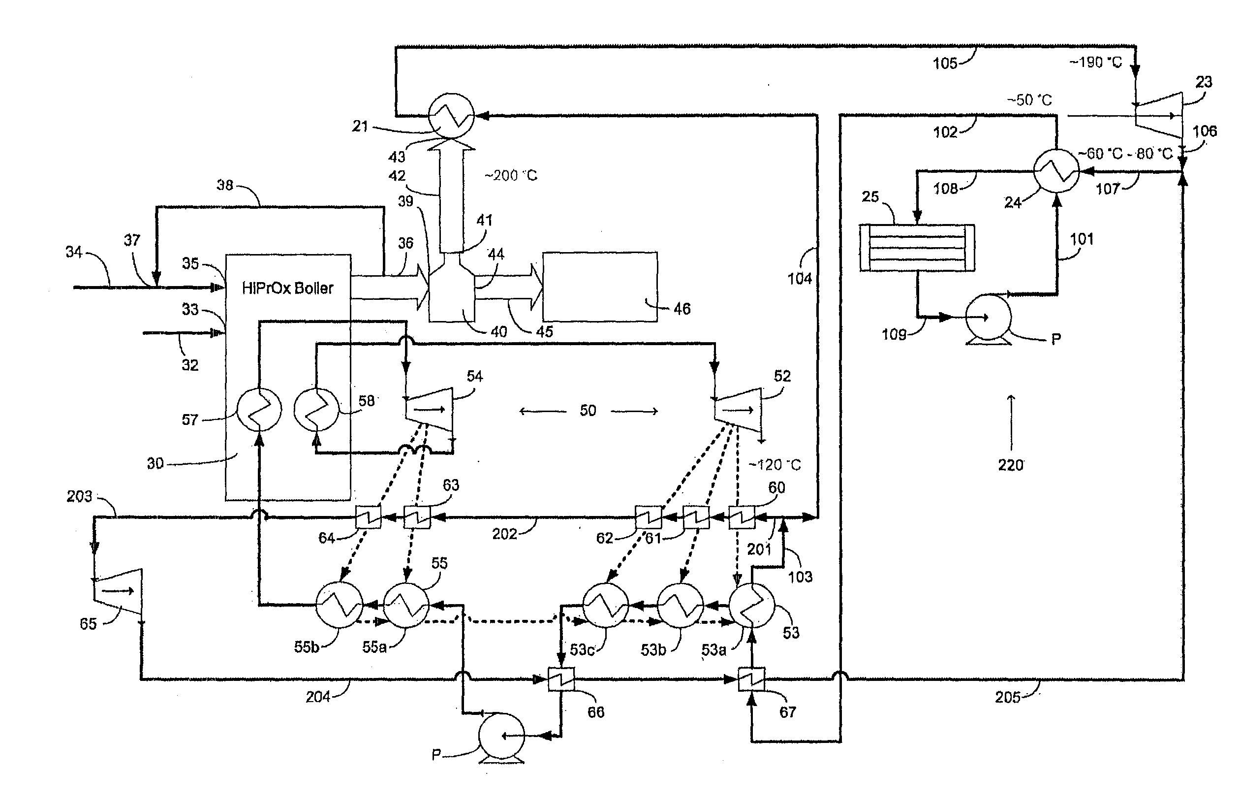
The present invention provides a hybrid Rankine cycle that uses two different fluids, water-steam and organic fluids, under both high pressure and ambient pressure combustion modes to increase thermal power cycle efficiency. This cycle configuration allows optimal coupling of streams which are more suitable source for the SRC and streams which are more suitable source for the ORC, resulting in maximization of energy conversion and overall efficiency. The hybrid Rankine cycle is expected to increase the cycle efficiency of subcritical and supercritical systems. Additionally, the invention includes a turbine system that reduces the size of the condenser for the first working fluid.

Problems solved by technology

Unfortunately, fossil fuels are also the main source of pollutants; greenhouse gases as well as criteria air contaminants The low efficiencies of conventional steam Rankine cycle systems exacerbate the problem with these emissions.
In general, energy losses are inevitable in the course of any Rankine cycle's operation.
This means that even with the best steam Rankine cycles available today, there are still losses of 60%, and as a result, SRC efficiencies remain low.
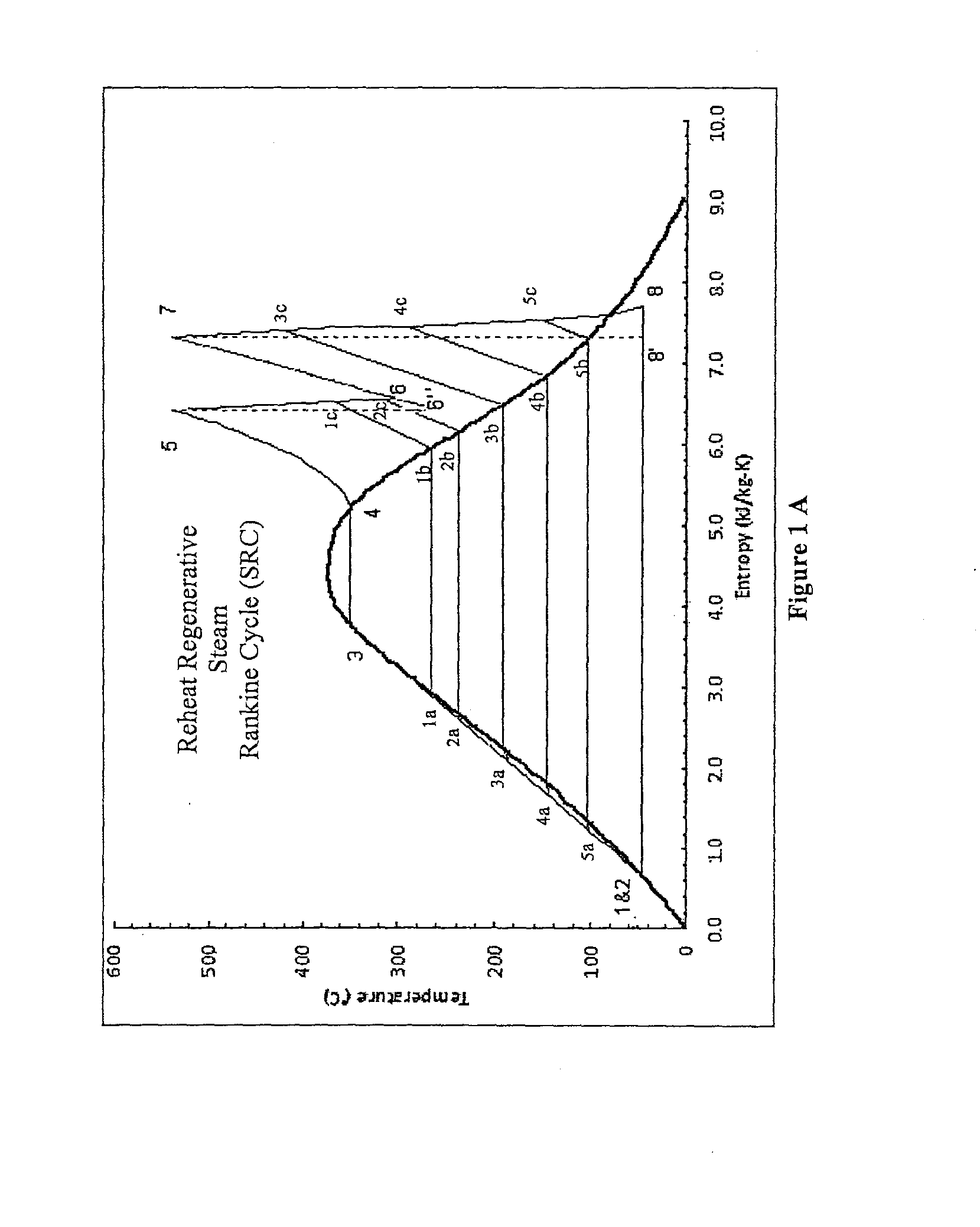
It can be seen that extraction points 1c, 2c, 3c, 4c and 5c are in the superheated region: the higher the temperature of the point 5 and 7, the higher the extraction temperature of points 1c, 2c, 3c, 4c and 5c will be giving a higher temperature difference between the extraction steam and feedwater, which results in greater irreversibility or exergy loss of the regeneration process.
Even if a heat sink source with very low temperature exists such as cooling water in winter or deep lake water (with a temperature of near 4° C. year round below approximately 20 m), the condensing temperature will not be sufficiently low to take full advantage of the cooling water.
This is because the volumetric flow rate of steam, under such vacuum conditions, is so high that it results in huge dynamic losses in the turbine and actually lowers the turbine efficiency; meanwhile, the steam becomes very wet in the course of its expansion prior to reaching the condenser.
Water droplets in the wet steam will cause serious erosion of turbine blades and will result in safety issues.
Of the 60% heat losses in SRC, the majority are due to exhausted heat discharged to the heat sink by steam-water condensation, which is unrecoverable energy loss.
For instance, a system with a turbine entry temperature of 565° C. and condenser temperature of 10° C. gives a theoretical Carnot efficiency of about 66%, but the actual cycle efficiency is about 40%, which means that an increase in efficiency of about 26% may still be attainable overall in theory, but not feasible with water-steam as the working fluid.
Again, these losses are less suitable for recovery with water-steam as the working fluid.
The above prior art systems and other systems such as those disclosed in U.S. Pat. Nos. 7,287,381, 7,096,665, 7,942,001 and 7,891,189 generally follow the above conventional configurations and / or approaches to SRC efficiency improvement, and inherit the disadvantages associated with those approaches.

Method used


Image

  • Hybrid rankine cycle
  • Hybrid rankine cycle
  • Hybrid rankine cycle

Examples


Embodiment Construction

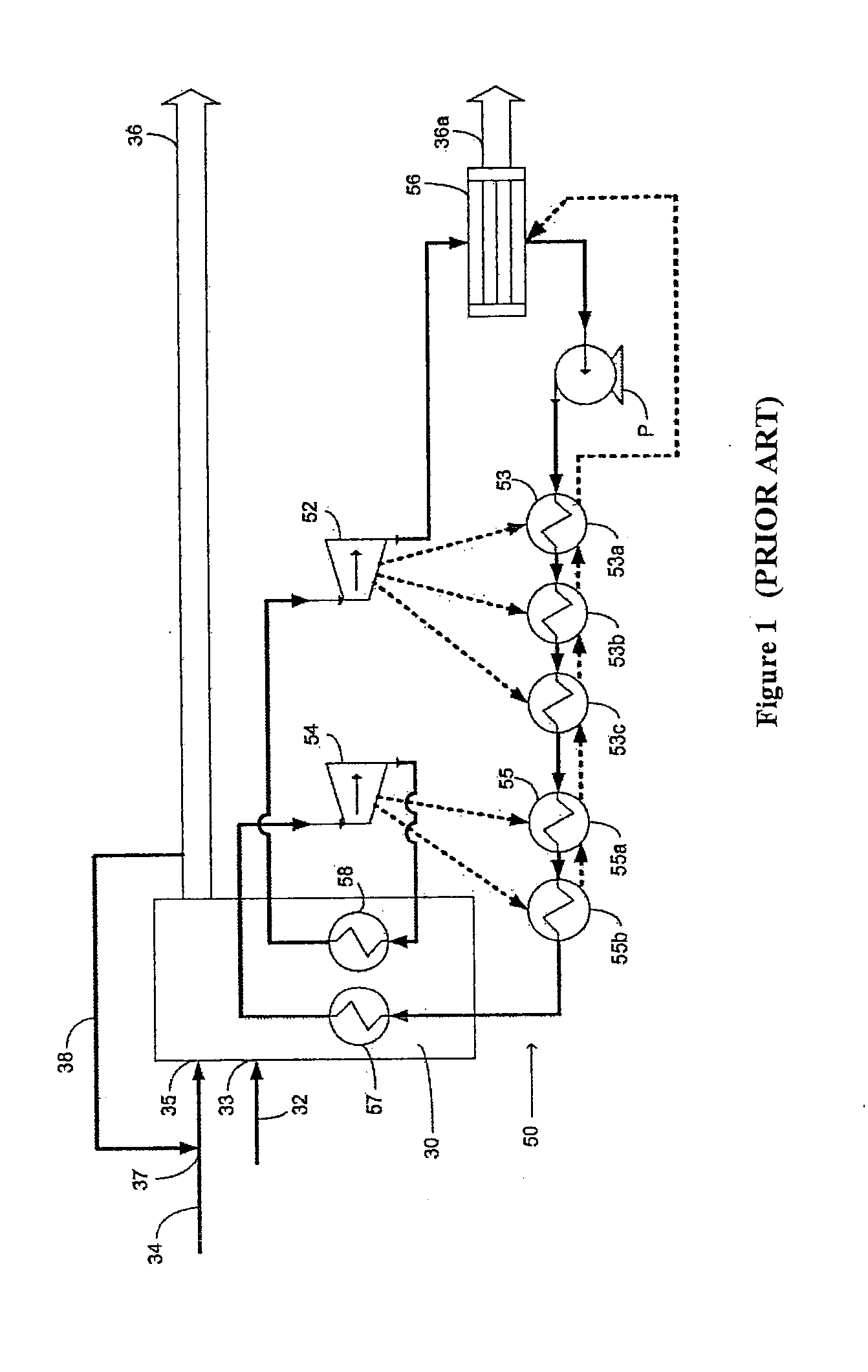
[0039]FIG. 1 shows a schematic conventional layout of a reheat regenerative steam Rankine cycle thermal energy conversion system 50 of the prior art. FIG. 1A shows a corresponding temperature-entropy (T-S) diagram of the prior art system of FIG. 1.

[0040]The Rankine cycle system of FIG. 1 typically comprises a boiler or furnace 30 which is fed by a fuel supply from line 32 at a fuel inlet 33, and may optionally be fed by an air or oxygen supply from line 34 at an air or oxygen inlet 35. Flue gas generated by the combustion leaves furnace 30 in flue gas line 36. Optionally, a recirculation stream can be separated from the flue gas stream in flue gas line 36, to be selectively recirculated back in flue gas recirculation line 38 to be reintroduced to the furnace in a suitable manner, either through a separate inlet (not shown) or by joining the air or oxygen supply in line 34.

[0041]In Rankine cycle 50 of FIG. 1, expanded working fluid leaves an intermediate pressure / low pressure turbine...


PUM


Abstract

A system using hybrid Rankine cycles is provided. The system includes a first Rankine cycle system using a first working fluid, the first system producing exergy loss and residual energy from at least one of turbine extraction, turbine condensation and boiler flue gas; and a second Rankine cycle system using a second working fluid to recover the exergy loss and residual energy. The second working fluid comprises a first stream and a second stream, wherein the first stream exchanges heat with the first system via at least one first heat exchanger, and the second stream exchanges heat with the first system via the at least one first heat exchanger and at least one second heat exchanger. A turbine of the first system is configured to allow the first working fluid to exit at a sufficiently high pressure and temperature to provide heat to the second system instead of expanding to a low pressure and temperature and discharging heat to ambient using a condenser.

Description

TECHNICAL FIELD OF THE INVENTION[0001]The present invention relates generally to energy recovery and particularly to systems and methods for thermal energy conversion.BACKGROUND OF THE INVENTION[0002]Thermal power conversion using fossil fuel is a technology used by major power utilities to generate electricity. Thermal power cycles typically convert chemical energy of fossil fuels into thermal energy of flue gas through combustion. The thermal energy from flue gas is transferred to pressurized water-steam which drives turbines through steam expansion, releasing the remaining thermal energy of the exhaust steam to the ambient environment through condensation, with repressurization of the condensed water for the next cycle. Such energy conversion cycle with water-steam as a working fluid in turbines is known as steam Rankine cycle (SRC). Although water-steam is the predominant working fluid for conventional power cycles, it is possible to use other working fluids as well. Other commo...

Claims


Application Information

Patent Timeline
Patent Type & Authority Applications(United States)
IPC IPC(8): F01K7/22F01K23/04F01K25/10F01K7/40
CPCF01K7/22F01K7/40F01K25/103F01K25/10F01K23/04F01K25/08F01K25/106F22B1/1838Y02E20/34F01K7/34F01K7/38F01K7/42F01K7/44
Inventor CLEMENTS, BRUCE R.WU, LIJUNPOMALIS, RICHARDZHENG, LIGANG
Owner HER MAJESTY THE QUEEN & RIGHT OF CANADA REPRESENTED BY THE MIN OF NATURAL RESOURCES
Learn More