Detection units and methods for detecting a target analyte

a detection unit and analyte technology, applied in the field of detection units and methods for detecting targets, can solve problems such as difficult detection

Inactive Publication Date: 2015-10-29
SCANOGEN
View PDF0 Cites 8 Cited by
  • Summary
  • Abstract
  • Description
  • Claims
  • Application Information

AI Technical Summary

Benefits of technology

[0021]In one embodiment of any aspects of the invention, target analyte binding occurs prior to attachment of the filament to the detection unit. According to this embodiment, the target analyte is exposed to the filament wherein binding of the analyte to the filament occurs. Following exposure of the target analyte to the filament, the filament is then attached to the detection unit under conditions such that target analyte bound to the filament is not disrupted.
[0024]Another aspect of the invention is a method to electrically detect single elongated conductive and semi-conductive nanoparticles. The method consists of providing a substantially flat surface with at least two conductive strips with a non-conductive gap between them. Providing elongated particles with their longest dimension longer than the non-conductive gap, preferably between 100 nm and 10 μm long. One or more particles can get close to the surface when one or more forces act on the particles. Particles on the surface can be detected if they bridge two strips significantly reducing the electrical resistance between them.
[0041]In one embodiment, the method is used to detect a single nucleotide of interest in the target nucleic acid. In one embodiment of the method, the unpaired nucleotides in the discontinuous strand of the linear DNA molecule share 100% complementarity with the target nucleic acid containing the single nucleotide of interest, such that supercoiling of the linear DNA molecule occurs only if the target nucleic acid of interest containing the single nucleotide of interest is present in the sample and wherein supercoiling will not occur when the only difference in the target nucleic acid is a different nucleotide at the single nucleotide of interest, such that the method can be used to discriminate between target nucleic acids that differ by only a single nucleotide.

Problems solved by technology

Although this property change, in theory, is detectable, it is difficult to detect, due in part to interference from non-specific binding events.

Method used


Image

  • Detection units and methods for detecting a target analyte
  • Detection units and methods for detecting a target analyte
  • Detection units and methods for detecting a target analyte

Examples


example 1

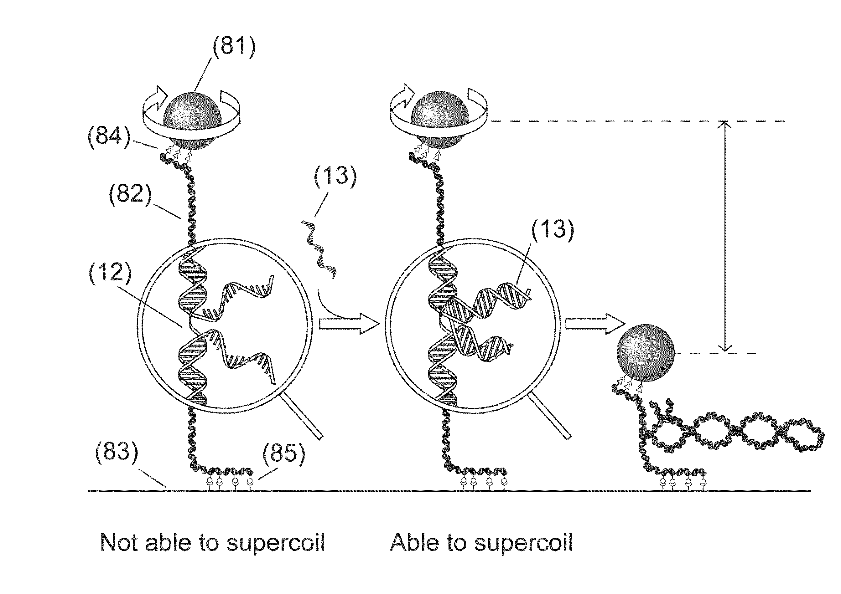
[0148]Disclosed is a strategy to detect oligonucleotide analytes. In this exemplified detection technique, the hybridization of the target analyte to a DNA molecule restores the capacity of the DNA molecule to supercoil. The detection unit in this example includes a double stranded DNA molecule (dsDNA), 2.5 μm long, attached at one end to a glass surface and at the other end to a 1 μm magnetic bead—a configuration used in magnetic tweezers experiments (see Strick et al., Science 271, 1835-1837 (1996); Celedon et al., Nano Lett 9, 1720 (2009)). (FIG. 9A). A magnetic field pulls the bead away from the glass surface extending the DNA molecule. The DNA molecule has a discontinuous strand and therefore is not able to supercoil (Voet et al., Biochemistry. 4th edn, John Wiley & Sons, Inc., Hoboken, N.J., USA, 2011). The two unpaired overhangs at both sides of the discontinuous strand are each complementary to adjacent regions of the target molecule. Hybridization of a target molecule to bo...

example 2

[0158]This example discloses a method to detect the presence of nanorods contacting a flat surface. The method can be used to detect supercoiling of a DNA molecule if the molecule is previously attached at one end to a nanorod and at the other end to the flat surface.

[0159]The presence of nanorods contacting a gold pattern was detected from the drop in electrical resistance between gold stripes (FIG. 10). A resistance change from 1-10 GΩ in the absence of a bridging nanorod to 30-40 kΩ in the presence of a nanorod was measured. Simple hand held testers can detect this resistance change.

[0160]Nanorods were prepared by electrodeposition into the 200 nm diameter pores of an aluminum oxide template membrane (Whatman, Springfield Mill, Kent, England), similar to previously published protocols. (Celedon et al., Nano Lett 9, 1720 (2009)) The nanorods formed by filling the pores of the membrane by the deposited material. Segments were deposited by changing the electrolytic solution. The tem...

example 3

[0162]This example discloses a method to detect the presence of a particle in the vicinity of an array of light sensors, such as complementary metal-oxide-semiconductor (CMOS) and charge-coupled devices (CCD), normally used in digital video cameras. The method can be used to detect supercoiling of a DNA molecule if the molecule is previously attached at one end to a particle and at the other end to the surface of the sensor.

[0163]The presence of 1 μm beads (Myone, Life Technologies) was detected on the surface of a CCD camera. Beads were placed directly on the surface of the sensor. A 2 μl drop of solution containing the beads was placed on the surface. After few minutes, the water in the solution had evaporated and an image of the surface of the sensor was obtained using an optical microscope (FIG. 11A), showing a large number of beads on the surface. The sensor was then introduced in a sealed box having only one small hole through which light from a light-emitting diode (LED) ente...


PUM

PropertyMeasurementUnit
diameteraaaaaaaaaa
diameteraaaaaaaaaa
resistanceaaaaaaaaaa

Abstract

The present application relates to detection units and methods for detecting one or more target analytes in a sample. The detection unit provides a first and second surface connected by a filament which is capable of binding the target analyte in the sample. Double-stranded DNA molecules are provided having a continuous strand and a discontinuous strand, and an active segment that is designed to hybridize to a target nucleic acid of interest, where the continuous strand has between 0 and 100 unpaired nucleotides in the active segment and the discontinuous strand has between 5 and 100 unpaired nucleotides at its 3′ end and / or its 5′ end. The unpaired nucleotides in the continuous strand can form a secondary structure, such as a loop. The methods provide for the detection of the target analyte through the generation of a detectable signal, such as supercoiling, following the binding of the target analyte to the filament and can be used to detect nucleic acids of interest including single nucleotide polymorphisms or somatic mutations.

Description

CROSS REFERENCE TO RELATED APPLICATION[0001]This application claims the benefit of U.S. Provisional application No. 61 / 983,684, filed Apr. 24, 2014, the entire disclosure of which is incorporated herein by reference.SEQUENCE LISTING[0002]The present application contains a Sequence Listing, which has been submitted via EFS-Web and is hereby incorporated by reference in its entirety. The ASCII copy of the Sequence Listing was created on Apr. 21, 2015, is named Sequence.txt, and is 2 kilobytes in size.FIELD OF THE INVENTION[0003]The present invention relates generally to detection units and methods for detecting a target analyte such as natural, synthetic, modified or unmodified nucleic acids or proteins in a sample for general diagnostic purposes.BACKGROUND OF THE INVENTION[0004]Many detection systems for determining the presence or absence of a particular target analyte in a sample are known. Examples of detection systems for detecting analytes include immunoassays, such as an enzyme...

Claims


Application Information

Patent Timeline
Patent Type & Authority Applications(United States)
IPC IPC(8): C12Q1/68C12N15/11
CPCC12Q1/6825C12N15/11C12N2320/10C12N2310/532C12Q1/6834C12N15/10C12N15/111C12N2310/14C12N2310/141C12Q2537/125C12Q2563/143C12Q2563/149C12Q2565/131
Inventor CELEDON, ALFREDO ANDRES
Owner SCANOGEN
Why Eureka
Try Eureka