
Synthetic microparticles

a technology of synthetic microparticles and ash, applied in the field of synthetic microparticles, can solve the problems of low yield, inability to exercise direct control over the composition of the product produced, and contamination of various levels of ash, so as to promote the pre-reaction of oxide components and low cost

Active Publication Date: 2015-11-05
JAMES HARDIE TECH LTD
View PDF10 Cites 11 Cited by
  • Summary
  • Abstract
  • Description
  • Claims
  • Application Information

AI Technical Summary

Benefits of technology

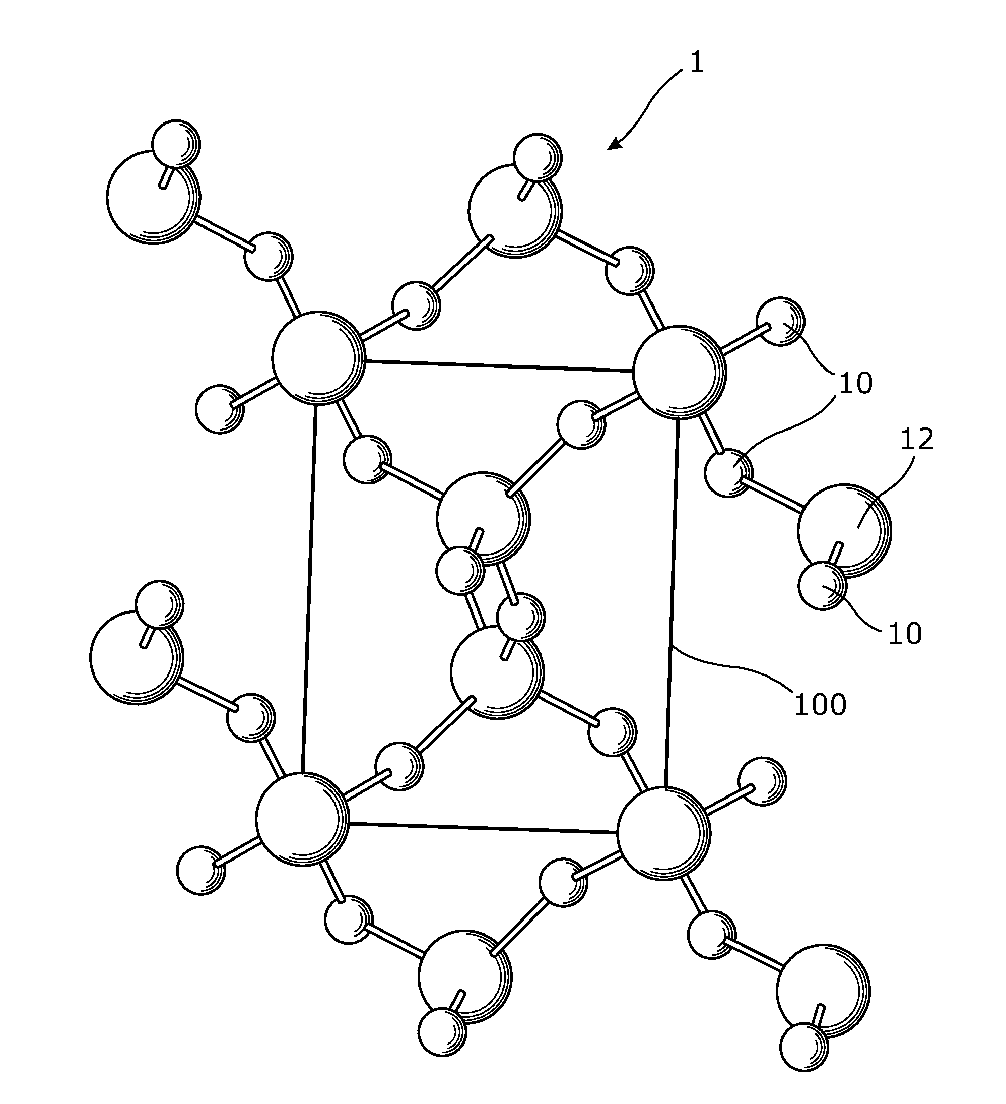
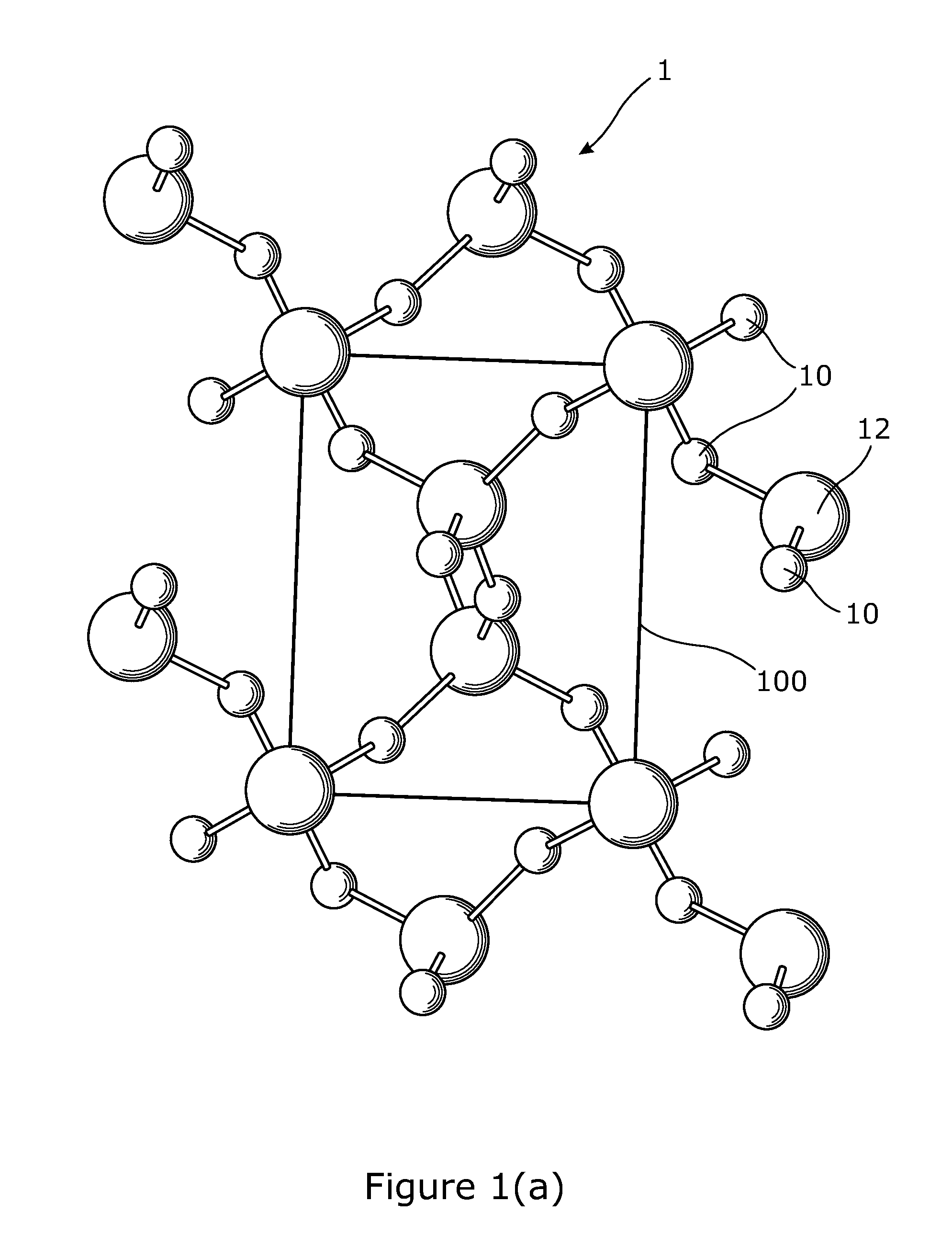
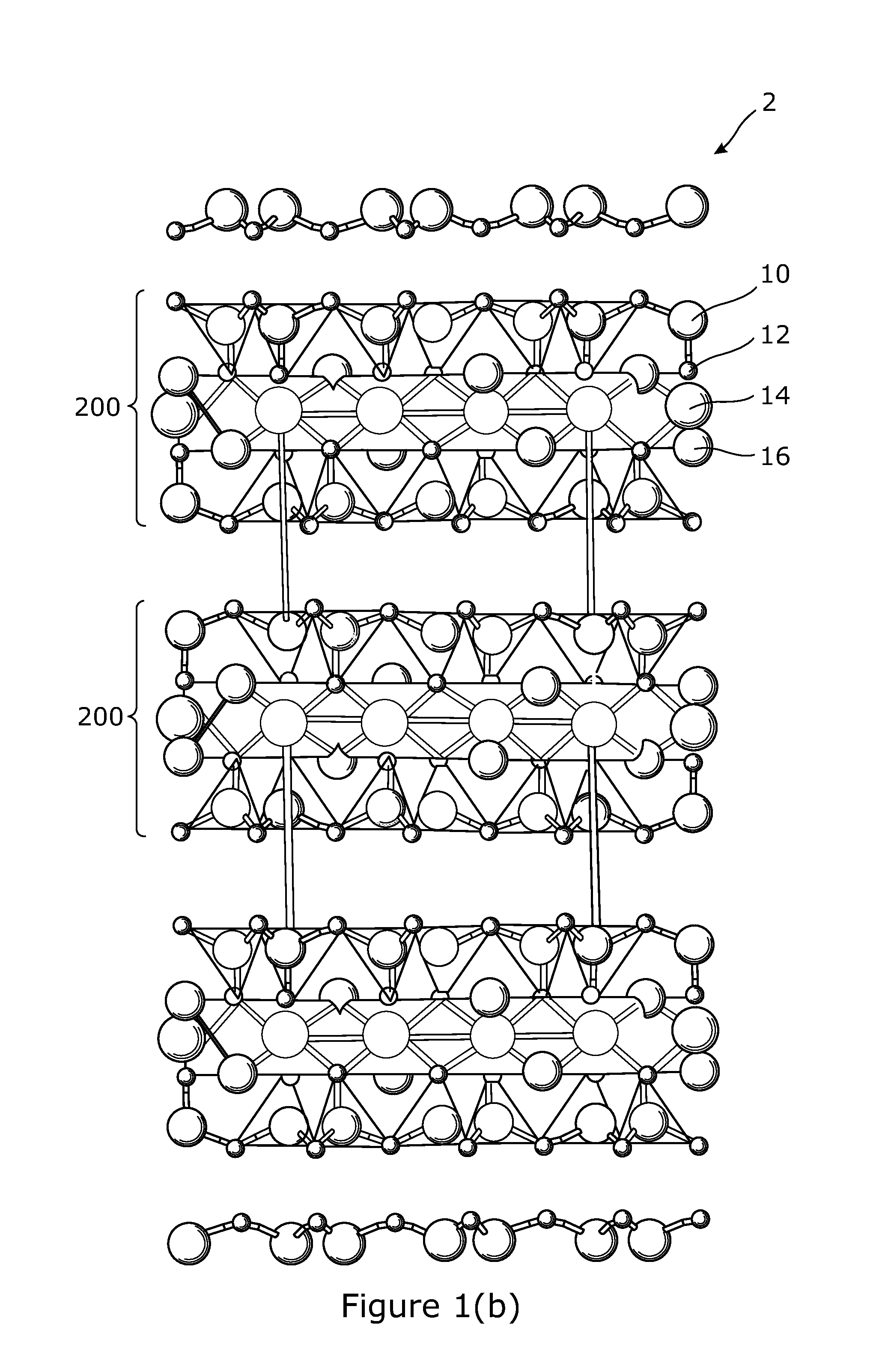
The patent is for a method for making synthetic microspheres using an aluminosilicate material, which can be either calcined or non-calcined. The use of fly ash as a primary component is preferred. The method involves adding a blowing agent and / or binding agent to the primary material, which is then agglomerated. The resulting precursor is then dried to remove moisture and reduce rupturing of the microspheres during the firing step. The combination of the at least one pre-selected chemical with the primary component and binding agent also helps to reduce rupturing. Overall, the method improves the quality and production of synthetic microspheres.

Problems solved by technology

It is not uncommon for the ash to be contaminated with various levels of soot or unburnt carbonaceous material in periods of high power demand.
In this instance a supplier is unable to exercise any direct control over the composition of the product produced.
When considering density modifying particles produced by burning coal in power station furnaces, for example, cenospheres, the yield is low and secondary processing is required to separate these particles from the predominant form of ash.
Furthermore harvested microparticle products contaminated by other undesirable combustion by-products may be unfit for use.

Method used


Image

  • Synthetic microparticles
  • Synthetic microparticles
  • Synthetic microparticles

Examples


example 1

[0169]This example shows a range of formulations of agglomerated precursor particles made with Borax according to embodiments of the present disclosure. Precursor component compositions are shown in Table 4A and agglomerated precursor compositions are shown in Table 4B. To form a precursor particle into a fired microparticle, a furnace temperature was used with the given furnace conditions: max temperature 1500° C., residence time 0.3 to 3 sec., and a firing atmosphere listed in Table 3.

TABLE 3Firing AtmosphereEquivalence RatioO2N2CO2CH4H2Omol fraction0%70.82%9.41%0.94%18.82%

TABLE 4ARawCom-componentBlowingMaterialponent 12BinderAgentAdditivecompositionweight %OxideSiO258.652.3Al2O322.912.4B2O336.5Na2O21.816.3K2O1.14.7Li2O00MgO1.34.8CaO5.76.7BaO0.30.07Fe2O35.14.4TiO21.1Other100SiC100H2O - bound11.747.2

TABLE 4BFormula 1Formula 2Formula 3wt %PRECURSOR (after spray drying)Component 18743.565component 2043.522Binder101010Blowing agent222Additive111expressed as oxidesSiO254.154.154.1Al2O3...

example 2

[0170]Another embodiment of synthetic microparticles according to the present disclosure is shown in Table 5. This example shows analysis of synthetic microparticles in the form of synthetic hollow microspheres manufactured from precursor formulations provided in previous example, according to the present disclosure.

TABLE 5Formula 1Formula 2Formula 3Microparticlesatomic %O62.7862.0562.42Si19.0119.1419.08Al8.747.177.97B2.352.502.42Na2.42.52.5K0.51.30.9Li0.00.00.0Mg0.61.61.1Ca2.02.32.1Ba0.00.00.0Fe1.31.31.3Ti0.30.10.2Other0.50.50.5O:Si3.33.23.3Total Divalent2.73.93.3Total Monovalent2.93.83.3Total trivalent12.4010.9711.70

[0171]The microparticle size can have a wall thickness of about 1 to 100 microns, preferably from about 5 to about 15 microns, more preferably from about 3.13 to about 94 microns. The wall thickness can range from about 5% to about 15% of the diameter of the microparticles. The diameters of the microparticles can range from about 30 to about 1000 microns. Diameters of ...

example 3

[0172]This example shows typical spray drying conditions used to produce agglomerate precursors in certain preferred embodiments of the present disclosure.

[0173]Dryer: Bowen Engineering, Inc. No 1 Ceramic Dryer fitted with a two-fluid nozzle type 59-BS

[0174]Air nozzle pressure: about 20 psi

[0175]Cyclone vacuum: about 4.5

[0176]Inlet / Outlet temperature: about 550° C. / 120° C.

[0177]Chamber vacuum: about 1.6

[0178]Slurry solids: about 50%

[0179]Agglomerate precursors produced using these spray drying conditions had a suitable average particle diameter and particle diameter distribution for forming synthetic hollow microspheres therefrom.

[0180]Agglomerate precursors produced using these spray drying conditions had a suitable average particle diameter and particle diameter distribution for forming synthetic microparticles in the form of synthetic hollow microspheres therefrom.

[0181]One preferred method of the present disclosure advantageously provides a means for producing synthetic micropar...


PUM

PropertyMeasurementUnit
Fractionaaaaaaaaaa
Fractionaaaaaaaaaa
Fractionaaaaaaaaaa

Abstract

Disclosed herein are synthetic microparticles substantially free of monovalent and divalent metal elements and a method of forming such synthetic microparticles. The synthetic microparticle may be suitable for use as a density modifying filler. The synthetic microsphere can be made from an agglomerate precursor that includes an aluminosilicate material, such as fly ash, a blowing agent such as sugar, carbon black, and silicon carbide, and a binding agent. The synthetic microsphere is produced when the precursor is fired at a pre-determined temperature profile so as to form either solid or hollow synthetic microspheres depending on the processing conditions and / or components used. The synthetic microparticle is capable of being formed into a large range of predetermined shapes.

Description

BACKGROUND[0001]1. Field[0002]The present disclosure relates to synthetic microparticles and in particular to synthetic microparticles in the form of synthetic hollow microspheres.[0003]2. Description of the Related Art[0004]Any discussion of the prior art throughout the specification should in no way be considered as an admission that such prior art is widely known or forms part of the common general knowledge in the field.[0005]Microparticles in the form of ash particles from the burning of coal in power station furnaces are known. The composition of the ash changes depending on the type of coal being burnt and the combustion efficiency within the furnaces. It is not uncommon for the ash to be contaminated with various levels of soot or unburnt carbonaceous material in periods of high power demand. In this instance a supplier is unable to exercise any direct control over the composition of the product produced.[0006]When considering density modifying particles produced by burning ...

Claims


Application Information

Patent Timeline
IPC IPC(8): C04B14/30C04B14/04
CPCC04B14/308C04B14/303C04B14/04C04B14/301C04B14/30C04B28/02C04B20/0036B01J13/02
Inventor PHAM, THINHNATARAJAN, NANDAKUMAR
Owner JAMES HARDIE TECH LTD
Learn More