High-speed vehicle power and thermal management system and methods of use therefor

a technology of high-speed vehicles and thermal management systems, which is applied in the direction of turbine/propulsion fuel heating, efficient propulsion technologies, machines/engines, etc., can solve the problems of significant problems, the heat load generated during flight often exceeds the capacity of these conventional endothermic fuel cooling systems, and the cryogenic fuel sensible energy capacity is insufficient to provide platform-level cooling

Inactive Publication Date: 2015-11-05
THE UNITED STATES OF AMERICA AS REPRESETNED BY THE SEC OF THE AIR FORCE
View PDF21 Cites 14 Cited by
  • Summary
  • Abstract
  • Description
  • Claims
  • Application Information

AI Technical Summary

Benefits of technology

[0010]According to embodiments of the present invention, a thermal management and power generation system for a hypersonic vehicle includes a fluid supply having a volatile fluid and a fuel supply having an endothermic fuel. A first heat exchanger, fluidically coupled to the fluid supply, absorbs heat from a first portion of the hypersonic vehicle, which vaporizes the volatile fluid. A mixing apparatus, fluidically coupled to the first heat exchanger and the fuel supply combines the vaporized volatile fuel and endothermic fuel. A second heat exchanger, fluidically coupled to the mixing apparatus, absorbs heat from a second portion of the hypersonic vehicle and decomposes the endothermic fuel by endothermic pyrolysis. A heat engine, fluidically coupled to the first heat exchanger and the mixing apparatus, is configured to generate an electrical power for use by the hypersonic vehicle. The vaporized volatile fluid mixed with the endothermic fuel within the second heat exchanger reduces coking caused by the endothermic pyrolytic decomposition of the endothermic fuel as compared to an endothermic pyrolytic decomposition of an endothermic fuel not having a vaporized volatile fluid mixed therewith.

Problems solved by technology

High supersonic and hypersonic vehicles encounter (1) extremely challenging atmospheres that are characterized by fluctuating aerodynamic, thermal, and pressure loads and (2) a destructive environment comprising combustion products and oxygen.
However, for flights lasting longer than a few minutes, the heat loads are such that the sensible energy capacity of the cryogenic fuel is insufficient to provide platform-level cooling.
Still, the heat loads generated during flight often exceed the capacity of these conventional endothermic fuel cooling systems.
Yet significant problems remain.
While endothermic pyrolysis reactions break hydrocarbon fuels down into lighter species that can be more favorable in terms of ignition delay, coking of the heat exchanger channels due to nonselective carbon deposition remains a considerable challenge.
This spontaneous carbon deposition can dramatically restrict mission duration, and ultimately success, due to clogging and closure of the passages within the fuel system and heat exchanger.
In addition, these deposits reduce heat transfer and may create hot spots within the passages.
Still, the limited solubility of water in the fuel, the addition of water, and the complexity of a water injection loop for coking mitigation have limited its application in practical vehicle designs.
Another significant problem encountered by vehicles during hypersonic operations is electrical power generation.
Because the traditional Brayton cycle-based power generation approaches are impractical (largely due to the extremely high inlet air temperatures), electrical power for onboard subsystems is provided via lithium-ion batteries in most vehicles.
During longer flights, the battery-based system frequently fails to provide sufficient power.
In some situations, the use of batteries is precluded due to space and weight constraints.

Method used


Image

  • High-speed vehicle power and thermal management system and methods of use therefor
  • High-speed vehicle power and thermal management system and methods of use therefor
  • High-speed vehicle power and thermal management system and methods of use therefor

Examples


example 1

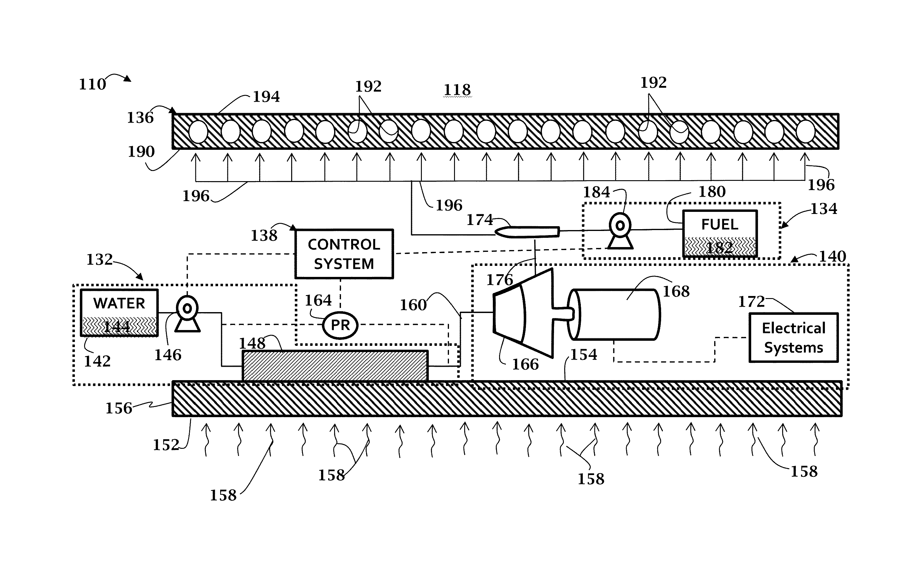
[0051]FIG. 7 is a schematic representation of a thermal management and power generation system according to an embodiment of the present invention, modeled using AMESim software (LMS Imagine.Lab®, LMS® International). The modeled thermal management generation system includes a first heat exchanger 280, a second heat exchanger 282, and a turbine 284. Conduits for water are illustrated as solid lines; conduits for fuel are illustrated as dashed lines.

example 2

[0052]FIG. 8 is a schematic illustrating results of modeling of the thermal management and power generation system of Example 1. Calculations were performed on AMESim software with units per 1000 lbs thrust and assuming about 5 steam wt %. As shown in FIG. 8, aerodynamic and / or vehicle system heating vaporizes the water, absorbing a heat load of approximately 25.4 kW to generate steam, which enters the turbine. The heat engine of the thermal management and power generation system can then be expected to generate over 3 kW of power for use onboard the vehicle. The endothermic fuel may also be used to cool the vehicle, absorbing a heat load of about 19 kW.

[0053]The present invention comprises a combined thermal management and power generation system and methods for using the same. An exemplary system may incorporate a heat engine fluid power generation system into an endothermic fuel cooling system. The presently disclosed system may be particularly useful for high supersonic and hype...


PUM


Abstract

A thermal management and power generation system for a hypersonic vehicle. The thermal management and power generation system comprising a fluid supply having a volatile fluid and a fuel supply having an endothermic fuel. A first heat exchanger, fluidically coupled to the fluid supply, absorbs heat from a first portion of the hypersonic vehicle, which vaporizes the volatile fluid. A mixing apparatus, fluidically coupled to the first heat exchanger and the fuel supply combines the vaporized volatile fuel and endothermic fuel. A second heat exchanger, fluidically coupled to the mixing apparatus, absorbs heat from a second portion of the hypersonic vehicle and decomposes the endothermic fuel by endothermic pyrolysis. A heat engine, fluidically coupled to the first heat exchanger and the mixing apparatus, is configured to generate an electrical power for use by the hypersonic vehicle. The vaporized volatile fluid mixed with the endothermic fuel within the second heat exchanger reduces coking caused by the endothermic pyrolytic decomposition of the endothermic fuel as compared to an endothermic pyrolytic decomposition of an endothermic fuel not having a vaporized volatile fluid mixed therewith.

Description

[0001]Pursuant to 37 C.F.R. §1.78(a)(4), this application claims the benefit of and priority to prior filed, co-pending Provisional Application No. 61 / 893,365, filed 21 Oct. 2013 (pending), the disclosure of which is incorporated herein by reference, in its entirety.RIGHTS OF THE GOVERNMENT[0002]The invention(s) described herein may be manufactured and used by or for the Government of the United States for all governmental purposes without the payment of any royalty.FIELD OF THE INVENTION[0003]The present invention relates generally to thermal management and power generation for hypersonic vehicles and, more particularly to systems and methods of thermal management and for management and generation of power for hypersonic vehicles.BACKGROUND OF THE INVENTION[0004]High supersonic and hypersonic vehicles encounter (1) extremely challenging atmospheres that are characterized by fluctuating aerodynamic, thermal, and pressure loads and (2) a destructive environment comprising combustion ...

Claims


Application Information

Patent Timeline
Patent Type & Authority Applications(United States)
IPC IPC(8): F02C7/224B64D33/08B64C30/00
CPCF02C7/224F05D2220/323B64D33/08B64C30/00B64C1/38B64D37/34B64D2033/024B64D2033/026F01K15/02F02C7/236F02K1/822F05D2220/62F05D2220/76F05D2220/80F05D2260/601F05D2300/514Y02T50/60Y02T90/40
Inventor REITZ, THOMAS L.BYRD, LARRY
Owner THE UNITED STATES OF AMERICA AS REPRESETNED BY THE SEC OF THE AIR FORCE
Why Eureka
Try Eureka