Method and apparatus for continuously and rapidly separating pyrolysis oil

A pyrolysis oil, fast technology, applied in the energy field to increase the degree of turbulence, simple and convenient operation, and avoid static electricity

Inactive Publication Date: 2012-12-19
JIANGSU QIANGLIN BIO ENERGY +1
View PDF3 Cites 5 Cited by
  • Summary
  • Abstract
  • Description
  • Claims
  • Application Information

AI Technical Summary

Problems solved by technology

However, the indirect distillation method is not suitable for large-scale industrial production because of its low output, high labor intensity, and large production safety hazards.

Method used


Image

  • Method and apparatus for continuously and rapidly separating pyrolysis oil
  • Method and apparatus for continuously and rapidly separating pyrolysis oil

Examples


Embodiment 1

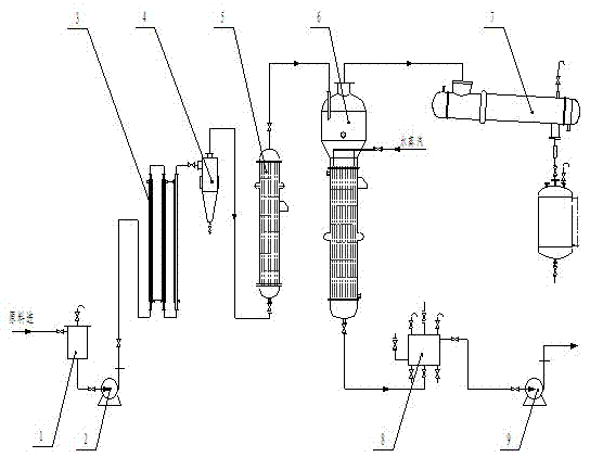
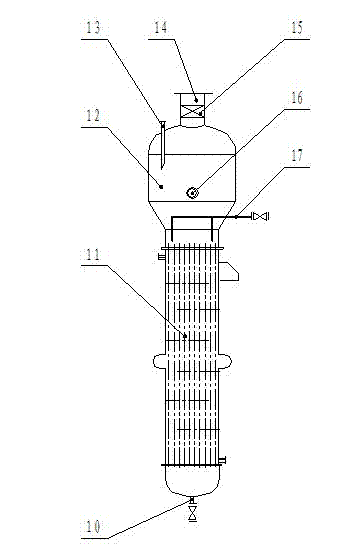
[0036] Example 1: Send waste plastic oil into a filter to remove particulate impurities below 100 mesh. Control the flow rate of the material at about 2m / s, and send it into the standpipe preheater by the feed pump and heat it to 80°C. Then the material enters the hydrocyclone to separate the remaining impurities in the material. Then it enters the evaporation preheater to preheat the material to 160°C, and finally enters the evaporator. The temperature of the evaporator is maintained at 190°C and steam is fed all the time, and about 50kg of steam at 160°C is fed into every 1000kg of plastic oil. Due to the existence of steam, the boiling point of the high boiling point components in the plastic oil is reduced, and the steam carries the distilled components into the condenser for condensation recovery. The unevaporated heavy components enter the discharge pump from the bottom of the evaporator and are sent to the finished product storage tank.

[0037] Table 1 is the proper...

Embodiment 2

[0039] Embodiment 2: waste rubber oil is sent into filter, removes particle impurity below 100 orders. Control the flow rate of the material at 3m / s, send it into the standpipe preheater by the feed pump and heat it to 100°C. Then the material enters the hydrocyclone to separate the remaining impurities in the material. Then it enters the evaporation preheater to preheat the material to 170°C, and finally enters the evaporator. The temperature of the evaporator is maintained at 190°C and steam is fed all the time, and about 80kg of steam at 180°C is fed into every 1000kg of plastic oil. Due to the existence of steam, the boiling point of the high boiling point components in the plastic oil is reduced, and the steam carries the distilled components into the condenser for condensation recovery. The unevaporated heavy components enter the discharge pump from the bottom of the evaporator and are sent to the finished product storage tank.

[0040] Table 2 is the property change ...


PUM

PropertyMeasurementUnit
densityaaaaaaaaaa

Abstract

The invention discloses a method and an apparatus for continuously and rapidly separating a pyrolysis oil, which is characterized in that a waste rubber, a waste plastic or the pyrolysis oil generated by thermal cracking of biomass is filtered and enters into a first preheater, the preheated pyrolysis oil enters into a cyclone hydraulic separator in a tangential direction, and enables spiral movement downwardly, the impurities spirally flow downwards to an outlet of a cone base due to inertial centrifugal force, the pyrolysis oil is discharged from a center tube at the top and enters into a second preheater for heating, then enters into an evaporator, the certain temperature is kept in the evaporator, steam is continuously introduced in the evaporator, the steam carries the distilled components enter into a condenser from the top of the evaporator together for condensate recovery, and the heavy components are sent from the bottom of the evaporator and cooled to obtain the finished product. The apparatus comprises a filter, a charge pump, the first preheater, the cyclone hydraulic separator, the second preheater, the evaporator in series, the top of the evaporator is connected to the condenser, the bottom of the evaporator is connected to a cooler. The method and apparatus for continuously and rapidly separating the pyrolysis oil have the advantages of high automation degree, and convenient and easy operation.

Description

technical field [0001] The invention belongs to the technical field of energy, and relates to a new technology for continuous and rapid separation of light components and heavy components of waste pyrolysis oil. Background technique [0002] my country is the world's largest consumer of rubber and plastics, and the production of waste rubber and waste plastics has also increased sharply. Waste rubber and waste plastics account for about 15% of the total solid waste. If the "black garbage" represented by waste rubber and the "white garbage" represented by waste plastics are not treated effectively, they will not only cause serious pollution to the environment, but also cause a huge waste of resources. For waste rubber and waste plastics, there are currently three main treatment methods: recycling, incineration, and cracking. For waste rubber and waste plastics that are not suitable for recycling and regeneration, incineration can recover energy, but it will cause serious s...

Claims


Application Information

Patent Timeline
Patent Type & Authority Applications(China)
IPC IPC(8): C10G53/02
CPCC10G1/10
Inventor 蒋剑春许玉应浩许彬张天健黄勇陈水根吴欢
Owner JIANGSU QIANGLIN BIO ENERGY
Why Eureka
Try Eureka