Sensing device, and sensing system and sensing method using the same

a sensing device and sensing system technology, applied in the field of sensing devices and sensing systems, can solve the problems of increasing the overall assay cost, complicated instrument setup, and low sensitivity (nm), and achieving the optimization of target capture efficiency, low cost but still effective biosensing, and simplified operation protocol

Active Publication Date: 2015-12-03
ACAD SINIC +1
View PDF3 Cites 8 Cited by
  • Summary
  • Abstract
  • Description
  • Claims
  • Application Information

AI Technical Summary

Benefits of technology

[0028]The present invention provides a sensing device, and a sensing system and a sensing method which are practically a biofunctionalized nanofluidic slits applied with classical fluorescence microscopy techniques, providing a simple, low-cost but still effective biosensing platform for kinetics studies. The sensing device includes a channel which depth is reduced to the sub-micrometer range, thus providing the following advantages of the present invention: (1) The drastic reduction of the diffusion length permits to operate in a reaction-limited regime with optimized target capture efficiency. Hence, all analyte molecules injected in the sensing device are analyzed, and the dissociation study can be simply implemented after completion of the association phase by reserving the fluid flow within the channel instead of injecting new buffer in the inlet, which results in a simplified operating protocol and reduced time of analysis; (2) a sampling volume reduction allows the device directly probing the immobilization element with conventional fluorescence microscopes without the need of using complicated and expensive setups, such as SPR, TIRFM, or QCM; (3) the signal to noise ratio is inversely proportional to the channel height: sub-micrometer channels thus offers signal to noise ratio of at least 100 on a large scale of dissociation constant KD, from the pM to the sub-μM range, that concerns most molecules of interests.
[0029]Moreover, the sensing device, sensing system and the sensing method of the present invention enables large sampling area over a number of pixels ensuring much reduced statistical errors (higher precision) than non-spatially resolved sensing platforms. More importantly, Fluorescence microscopy offers a limit of detection under the pM with no effect of analyte mass, thus allowing the sensing device and the sensing method of very high-affinity interactions and small molecules.
[0030]The present invention solves the prior art problems by providing: (1) shortened kinetic assay time due to the reversed flow operation while higher level of detection sensitivity can be achieved with a very simple set-up, (2) efficient target capture for minute sample analysis, and (3) spatiotemporally resolved reaction / binding kinetics allowing for low statistical error.

Problems solved by technology

However, these techniques require high-cost dedicated sensor surface and integration of optical or mechanical components which in turn increases overall assay costs and complicate the instrument setup.
SPR lacks spatial resolution and is expensive / complicated to implement, has low sensitivity (˜nM), much (1000×) higher amount of reagent consumption (10 μL), low multiplexing capability, high SPR chip cost (˜$300 / chip).
Moreover, QCM has no multiplexing capability and requires higher amount of reagent consumption and high chip cost (˜$100 / chip).
TIRFM (total internal reflection fluorescence microscopy) requires complicated apparatus, higher amount of reagent consumption.
The typical platforms described above have low sensitivity (nM range) and are not suitable for small amount of sample consumption.
The time it takes to detect specific biomolecules in a sample is mainly limited by the detector sensitivity and the time it takes for the lowest number of molecules that can be detected to reach the sensor.
. . ), when working with small sensing areas and low-concentration samples, the diffusion time is the main limiting factor for most microfluidic sensing platforms.
Though detection time can be reduced from several hours to several minutes using these methods, the main drawback of most of these methods is that they can be challenging to implement with highly complex manufacturing process.

Method used


Image

  • Sensing device, and sensing system and sensing method using the same
  • Sensing device, and sensing system and sensing method using the same
  • Sensing device, and sensing system and sensing method using the same

Examples


Embodiment Construction

[0048]The present invention will be apparent from the following detailed description, which proceeds with reference to the accompanying drawings, wherein the same references relate to the same elements.

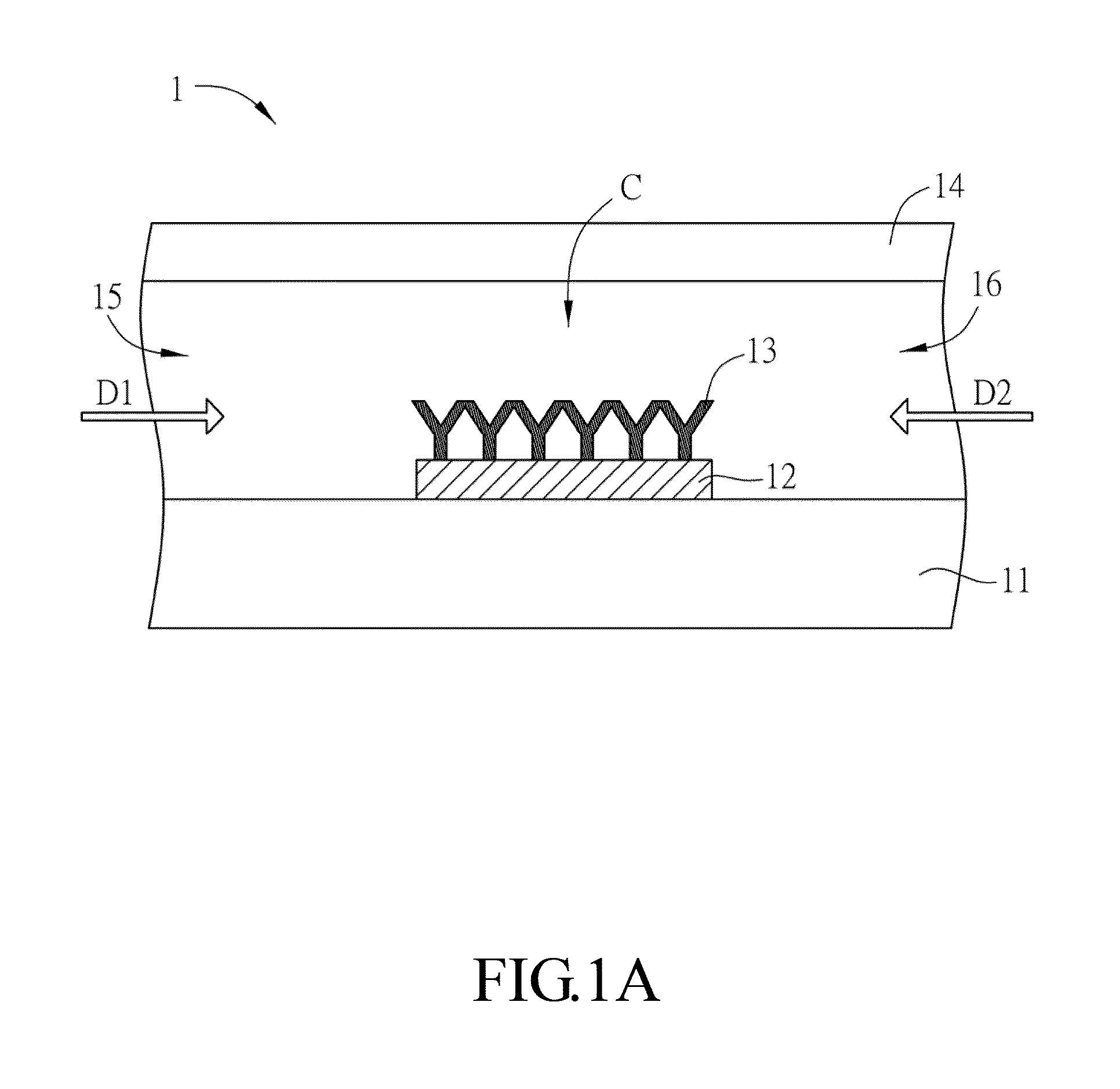
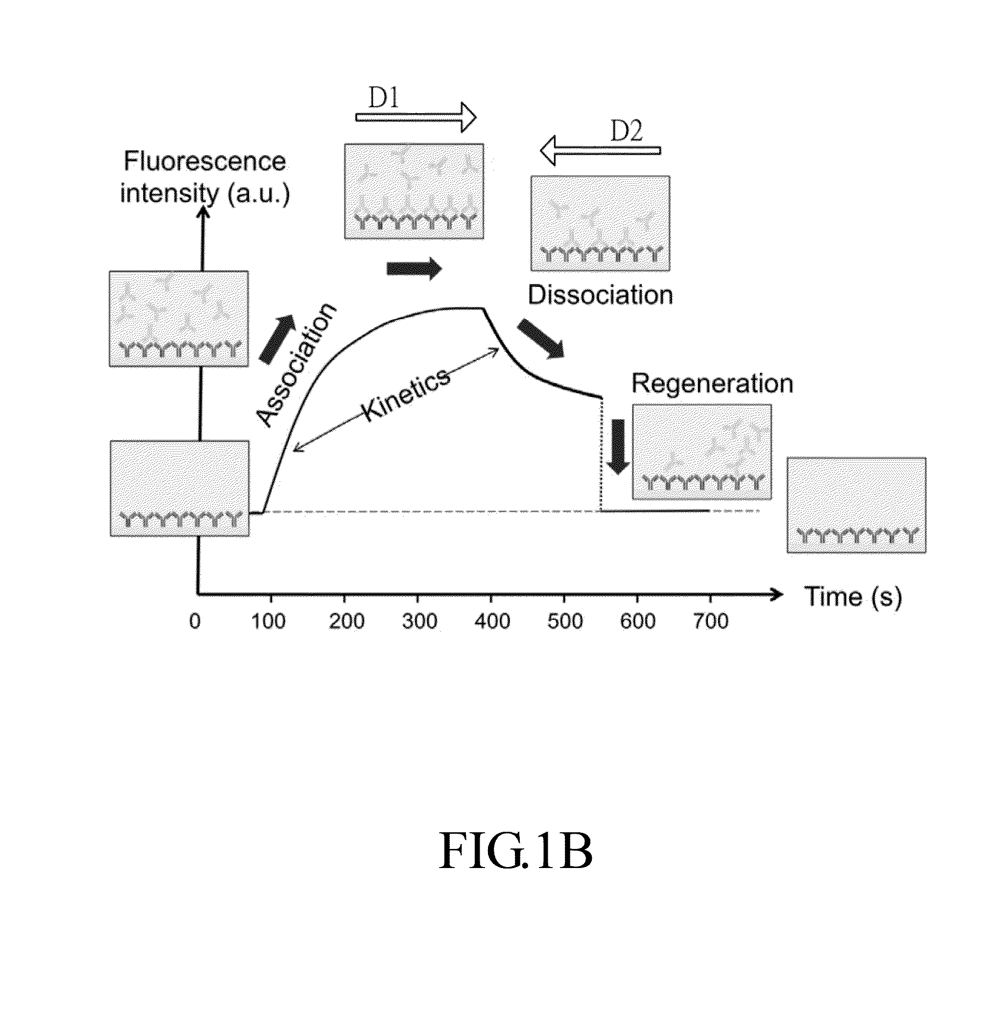
[0049]The present invention provides a rapid and cost-effective nanofluidic based immuno-biosensor platform for real-time kinetic measurement of protein-protein binding, which is not for limit sense. With the combination of conventional bench top fluorescence detection system and reversed buffer flow, both association and dissociation kinetics can be accessed in one single experiment without rinsing buffer loading step, which is generally impractical for typical microfluidic based immunoassays.

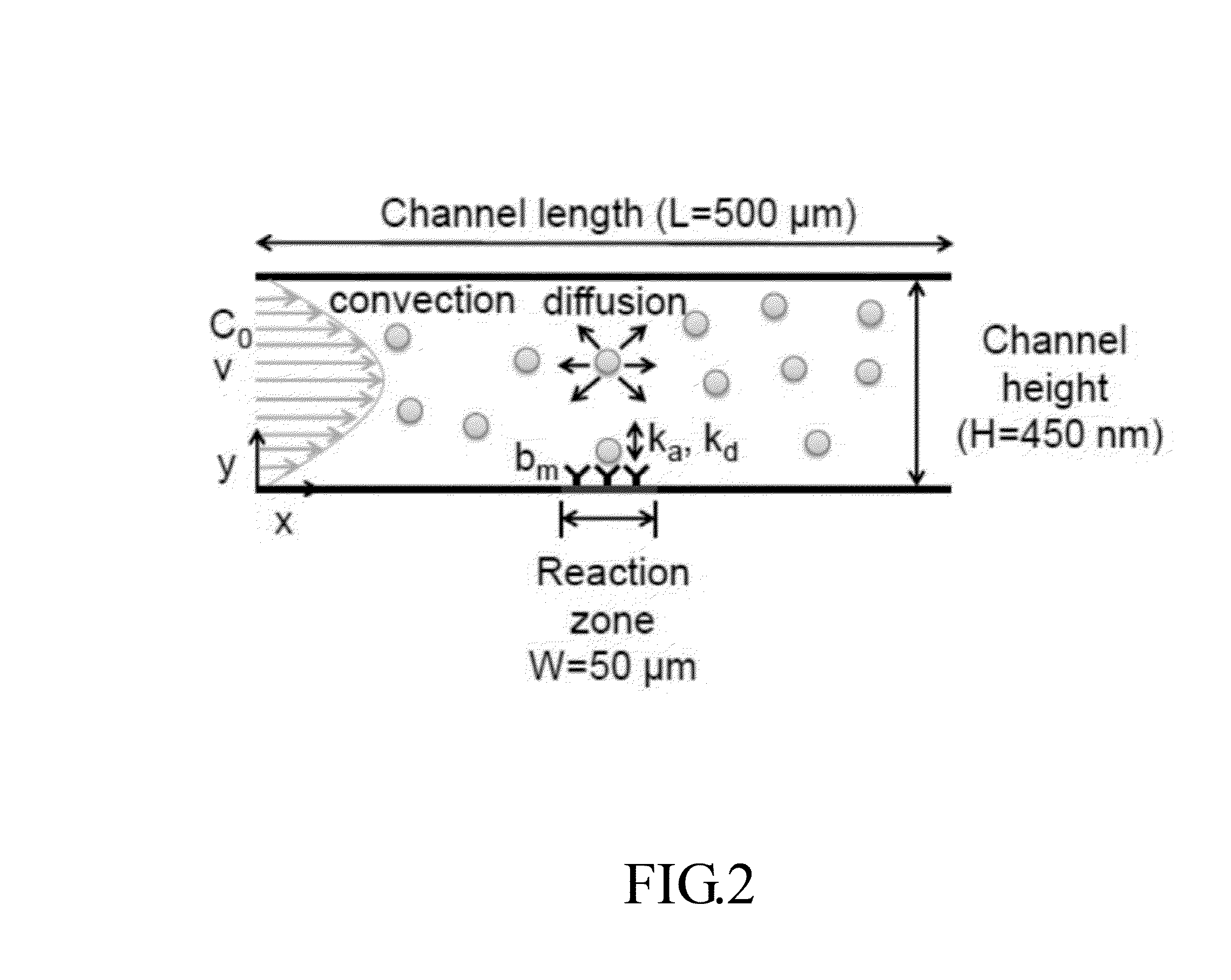
[0050]In the present disclosure, a model based on finite element method is developed to quantify kinetic constants of two representative protein-ligand binding pairs: streptavidin-biotin and mouse IgG / anti-mouse IgG. The good agreement of extracted rate constants between the devices of the prese...


PUM

PropertyMeasurementUnit
lengthaaaaaaaaaa
lengthaaaaaaaaaa
lengthaaaaaaaaaa

Abstract

A sensing device applied to an analyte molecule of a liquid sample and a buffer flow has at least one first inlet, at least one second inlet, a micro-flow channel, and at least one immobilization element. The first inlet is for inputting the liquid sample. The second inlet is for inputting the buffer flow. The micro-flow channel communicates with the first inlet and the second inlet. The immobilization element is for immobilizing sensing molecules for the analyte molecules. The analyte sample flow and the buffer flow, in the reverse direction, in the micro-flow channel enable the association and disassociation kinetics to be obtained. The present invention further provides a sensing system and a sensing method using the sensing device.

Description

CROSS REFERENCE TO RELATED APPLICATIONS[0001]This Non-provisional application claims priority to U.S. provisional patent application with Ser. No. 62 / 003,268 filed on May 27, 2014. This and all other extrinsic materials discussed herein are incorporated by reference in their entirety.BACKGROUND OF THE INVENTION[0002]1. Field of Invention[0003]The present disclosure relates to a sensing device, a sensing system and a sensing method for biofunctionalized nanoslits combined with fluorescence microscopy for ultra-fast sensing kinetics studies of labeled molecules but with simple / low-cost setup.[0004]2. Related Art[0005]Kinetic monitoring of protein interactions offers fundamental insights of their cellular functions and is a vital key in developing potential diagnostic test and bio-therapeutic treatment. Surface plasmon resonance (SPR) and quartz crystal microbalance (QCM) are currently standard commercialized technology routinely used in the field of pharmaceutical and life sciences, o...

Claims


Application Information

Patent Timeline
Patent Type & Authority Applications(United States)
IPC IPC(8): G01N21/76G01N33/543
CPCG01N33/54373G01N21/763B01L3/5027G01N33/557B01L2300/0636B01L2300/0877G01N21/6428G01N21/6458G01N2021/6439G01N33/54366
Inventor CHOU, CHIA-FULEICHLE, THIERRYLIN, YII-LIHTEERAPANICH, PATTAMON
Owner ACAD SINIC
Why Eureka
Try Eureka