
Reduced pressure double glazed glass panel

a reduced pressure technology, applied in climate change adaptation, building components, construction, etc., can solve the problems of large thickness of the entire double glazed glass panel, unsuitable for use in the window frame of residential houses, so as to increase the cooling efficiency in summer and increase the heating efficiency in winter.

Active Publication Date: 2015-12-10
NIPPON SHEET GLASS CO LTD
View PDF0 Cites 7 Cited by
  • Summary
  • Abstract
  • Description
  • Claims
  • Application Information

AI Technical Summary

Benefits of technology

The present invention relates to a type of glass panel used for heat insulation and heat shielding. The invention is based on a set of rules that help reduce the temperature difference between the glass panels when exposed to solar radiation. This reduction of temperature difference helps prevent the glass panels from bending or warping when exposed to sun. Using these rules, the invention provides a glass panel that is more durable and more resistant to bending when exposed to solar radiation. This makes the invention useful for a variety of applications wherein heat insulation and shielding are important.

Problems solved by technology

For example, in the case where the outside glass sheet and the inside glass sheet each have a thickness of 3 mm and the air layer has a thickness of 6 mm, the entire double glazed glass panel has a large thickness of 12 mm and is not suitable for use in window frames of residential houses.
This reduced pressure double glazed glass panel can not only increase the cooling efficiency in summer but also increase the heating efficiency in winter.
Therefore, when the reduced pressure double glazed glass panel is exposed to solar radiation and the temperature difference between the outside glass sheet and the inside glass sheet increases, the difference in thermal expansion between the glass sheets cannot be absorbed due to the deformation of the sealing material, which may cause bending of the glass sheets.
In particular, when the rigidity of the window frame is not sufficient, the frame is also bent subsequent to the bending of the glass sheets.
When the frame is bent, not only the operation of opening and closing the window cannot be performed smoothly, but also the frame and the panel may scrape against each other and be damaged.

Method used


Image

  • Reduced pressure double glazed glass panel
  • Reduced pressure double glazed glass panel
  • Reduced pressure double glazed glass panel

Examples


example 1

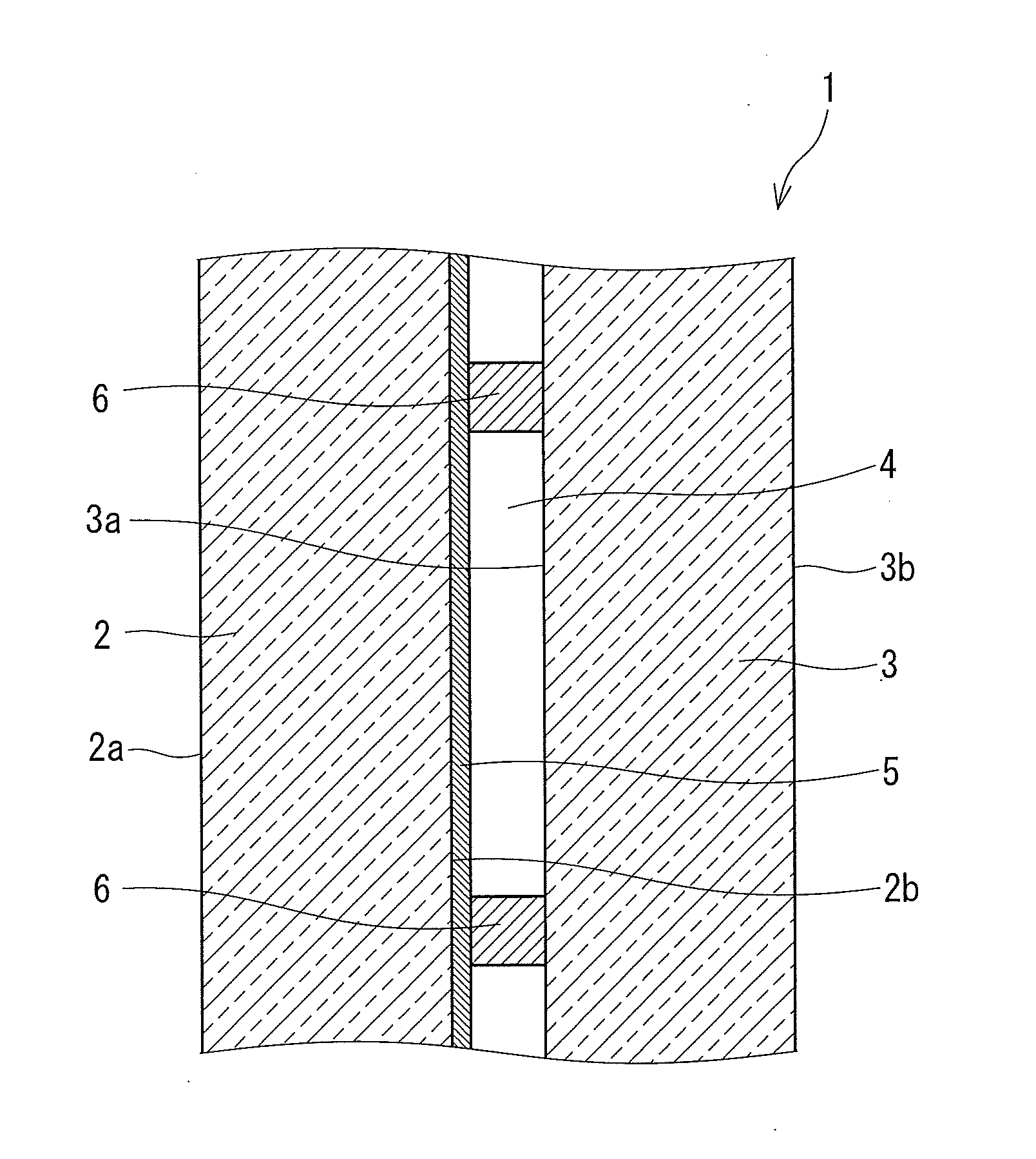
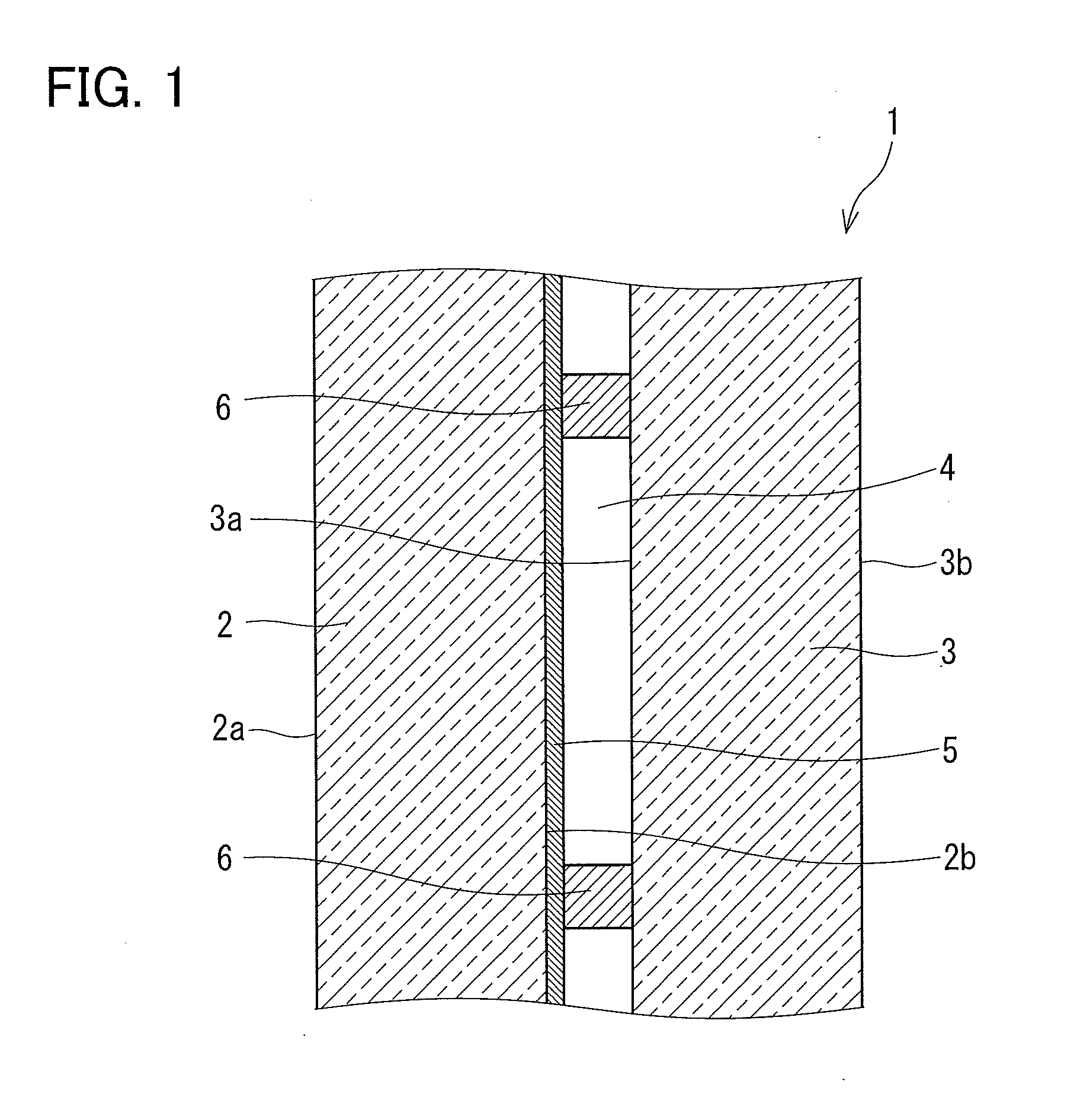
[0039]A 3.1 mm-thick outside glass sheet 2 on which a Low-E film 5 was formed was cut into a predetermined size, and a 3.1 mm-thick float glass sheet was prepared as an inside glass sheet 3. Stainless steel cylindrical spacers 6 with a diameter of 0.5 mm and a height of 0.2 mm were inserted between the pair of the outside glass sheet 2 and the inside glass sheet 3, these outside glass sheet 2 and the inside glass sheet 3 were sealed all along the peripheries thereof with a low melting glass to form a gap portion 4 therebetween, and then the gap portion 4 was evacuated to reduce the pressure therein. Thus, a reduced pressure double glazed glass panel 1 was obtained.

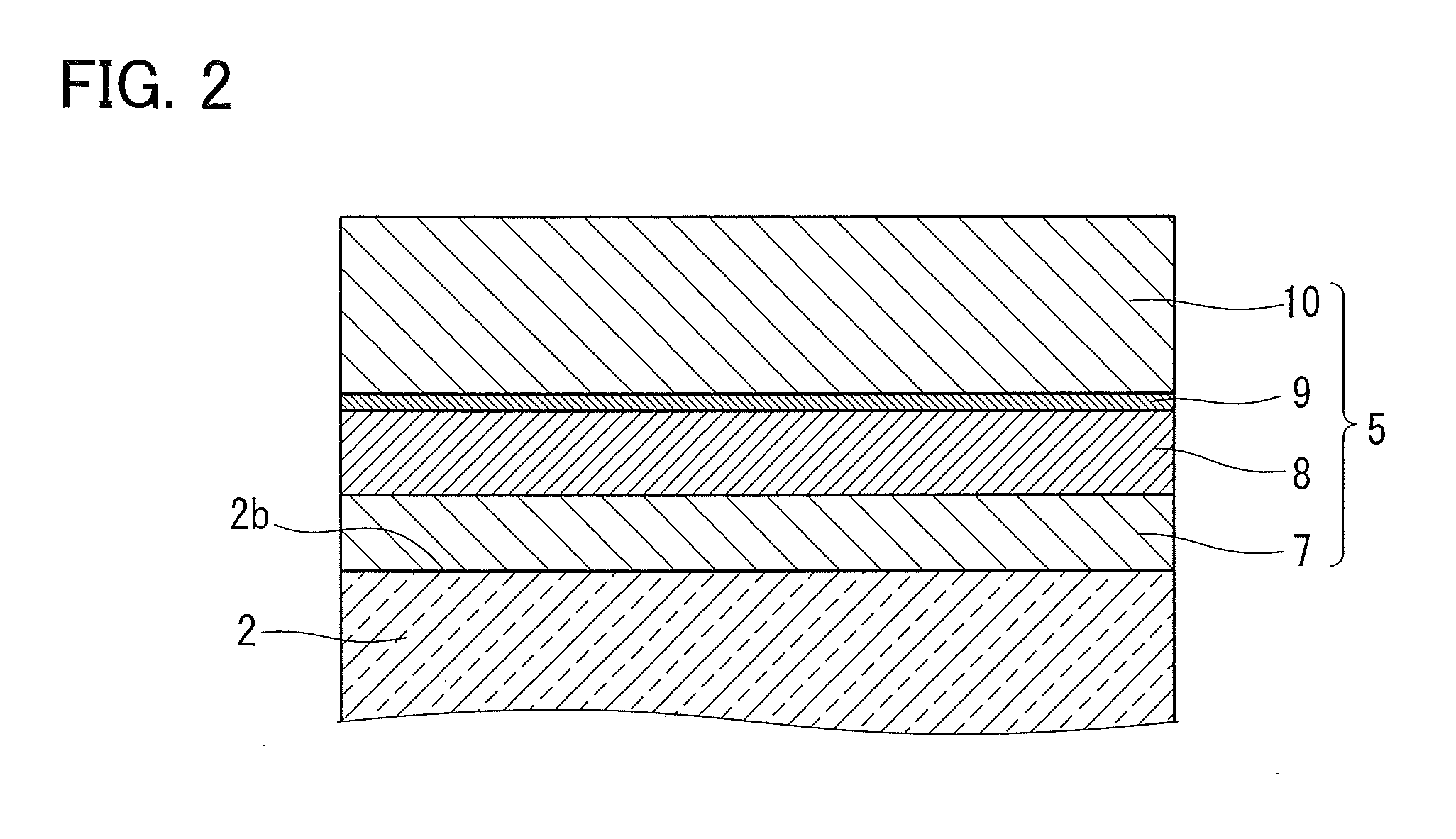
[0040]The Low-E film 5 was formed on the second surface 2b of the outside glass sheet 2 by reactive sputtering. The Low-E film 5 was formed by stacking a lower dielectric layer 7, a metal layer 8, a sacrifice layer 9, and an upper dielectric layer 10, each composed of a material shown in Table 1 and having a thickness show...

examples 2 to 15

[0044]In Examples 2 to 15, the reduced pressure double glazed glass panels 1 were produced in the same manner as in Example 1. As shown in Table 1, in Examples 2 to 15, the layered structures of the lower dielectric layer 7, the metal layer 8, the sacrifice layer 9, and the upper dielectric layer 10, the materials of these layers, and the thicknesses thereof were varied from those of Example 1. In Examples 2 to 15, the reduced pressure double glazed glass panels 1 were evaluated in the same manner as in Example 1. Table 2 shows the evaluation results. In Examples 2 to 17, the following relations hold: ∈≦0.067; 31≦RG(solar)≦40; (48−RG(solar))≦AG(solar)≦17; T(solar)≦52; AG(solar)≦{17.3−(0.07×RG(solar))+(20×∈)}; AF(vis)≦12; AF(400)≦14; SHGC≦0.50; and U value≦1.2. Here, since the above relations hold, the temperature difference ΔT between the outside glass sheet 2 and the inside glass sheet 3 is as small as 12.5° C. or less and thus the degree of bending is also low. Furthermore, in Exa...

example 16

[0045]In Example 16, the reduced pressure double glazed glass panel 1 was produced in the same manner as in Example 1. As shown in Table 1, in Example 16, the layered structures of the lower dielectric layer 7, the metal layer 8, the sacrifice layer 9, and the upper dielectric layer 10, the materials of these layers, and the thicknesses thereof were varied from those of Example 1.

[0046]Furthermore, in Example 16, a low-maintenance coating (see paragraph 0021 of JP 2008-505842 T) as a functional film that does not affect the optical properties of the outside glass sheet 2 on which the Low-E film 5 is formed was formed on the first surface 2a of the outside glass sheet 2. In Example 16, the low-maintenance coating is a layer formed by stacking a silicon oxide (SiO2) layer and a titanium oxide (TiO2) layer in this order. The thickness of the SiO2 layer is 9 nm, and the thickness of the TiO2 layer is 4 nm. This means that the thickness of the SiO2 layer is within a range of 5 nm or more...


PUM


Abstract

The reduced pressure double glazed glass panel of the present invention includes an outside glass sheet, an inside glass sheet, and a gap portion that are joined together, with the gap portion being formed between the glass sheets and sealed under reduced pressure. Here, the outside glass sheet has a first glass surface disposed to face the outdoor space and a second glass surface disposed to face the gap portion. A Low-E film is formed on the second glass surface. The following relations hold: (Emissivity of Low-E film ∈)≦0.067; 31%≦(Solar reflectance on First glass surface RG(solar))≦40%; (48−RG(solar))%≦(Solar absorptance on First glass surface AG(solar))≦17%; (AG(solar))≦{18.3−(0.07×RG(solar))+(20×∈)}%; (Solar heat gain coefficient SHGC)≦0.50; and (Thermal transmittance U value)≦1.2 W / m2·K or less. According to the present invention, it is possible to provide a reduced pressure double glazed glass panel having sufficient heat insulating and heat shielding properties and being less susceptible to bending when exposed to solar radiation.

Description

TECHNICAL FIELD[0001]The present invention relates to a reduced pressure double glazed glass panel most suitable for use in windows of buildings and the like.BACKGROUND ART[0002]As a means for increasing the heat shielding effect of a window of a building, a heat-ray absorbing glass is used. For example, Patent Literature 1 and Patent Literature 2 each disclose a heat-ray absorbing glass containing a specific combination of metal oxides. There have recently been developed double glazed glass panels having not only heat shielding properties but also heat insulating properties. For example, Patent Literature 3 discloses a double glazed glass panel including a heat-ray absorbing colored glass sheet provided on the outdoor side, a clear glass sheet provided on the indoor side, and a low emissivity film formed on the indoor-side surface of the outdoor-side heat-ray absorbing colored glass sheet.[0003]In a conventional double glazed glass panel, an air layer (or a gas layer such as an arg...

Claims


Application Information

Patent Timeline
Patent Type & Authority Applications(United States)
IPC IPC(8): E06B3/67E06B3/66
CPCE06B3/6612E06B3/6722E06B3/66Y02A30/249Y02B80/22E06B3/6715
Inventor INAOKA, DAISUKEKIJIMA, YOSHIFUMIMINAAI, TETSUO
Owner NIPPON SHEET GLASS CO LTD
Learn More