Solar Cells Comprising 2d-Perovskites

a technology of solar cells and perovskites, applied in the field of solar cells, can solve the problems of low quality films, negatively affecting solar cell performance, and unstable 3d-perovskites

Active Publication Date: 2015-12-10
THE BOARD OF TRUSTEES OF THE LELAND STANFORD JUNIOR UNIV
View PDF1 Cites 32 Cited by
  • Summary
  • Abstract
  • Description
  • Claims
  • Application Information

AI Technical Summary

Benefits of technology

[0021]Furthermore, reducing the dimensionality of the inorganic component from the 3d structure to the 2d structure results in an increase in bandgap. For example, the n=1 structure of the 2d-perovskite has a bandgap 2.57 eV compared to a bandgap of 1.61 eV for a 3d-perovskite of the form (MA)[PbX3]. The optimal value for the bandgap is 1.34 eV, which provides the highest theoretical efficiency for a single-junction solar cell. Thus, 2d-perovskites of n=1 typically have an unsuitable or at least much less-desirable bandgap for use as a light-absorbing layer than 3d-perovskites.
[0023]Notwithstanding the foregoing, the inventors recognized that 2d-perovskites possess certain other characteristics that would be advantageous in the context of a solar cell if a structure having a suitable bandgap could be identified. In particular, unlike their 3d analogs, 2d-perovskites readily form high-quality films that are relatively resistant to the effects of humidity.

Problems solved by technology

Simpler deposition methods, such as single-step spin coating or dipcoating, can be used, but they produce lower quality films, which negatively impact solar-cell performance.
Furthermore, 3d-perovskites are not stable in the presence of moisture, thereby requiring anhydrous processing conditions.

Method used


Image

  • Solar Cells Comprising 2d-Perovskites
  • Solar Cells Comprising 2d-Perovskites
  • Solar Cells Comprising 2d-Perovskites

Examples


example

Fabrication Solar Cell Fabrication

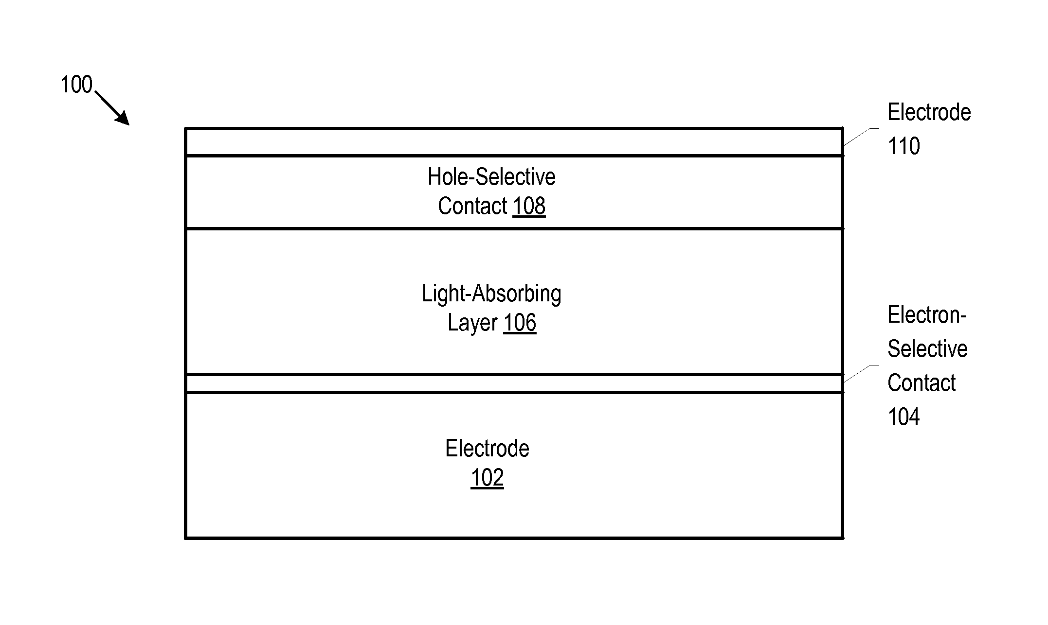
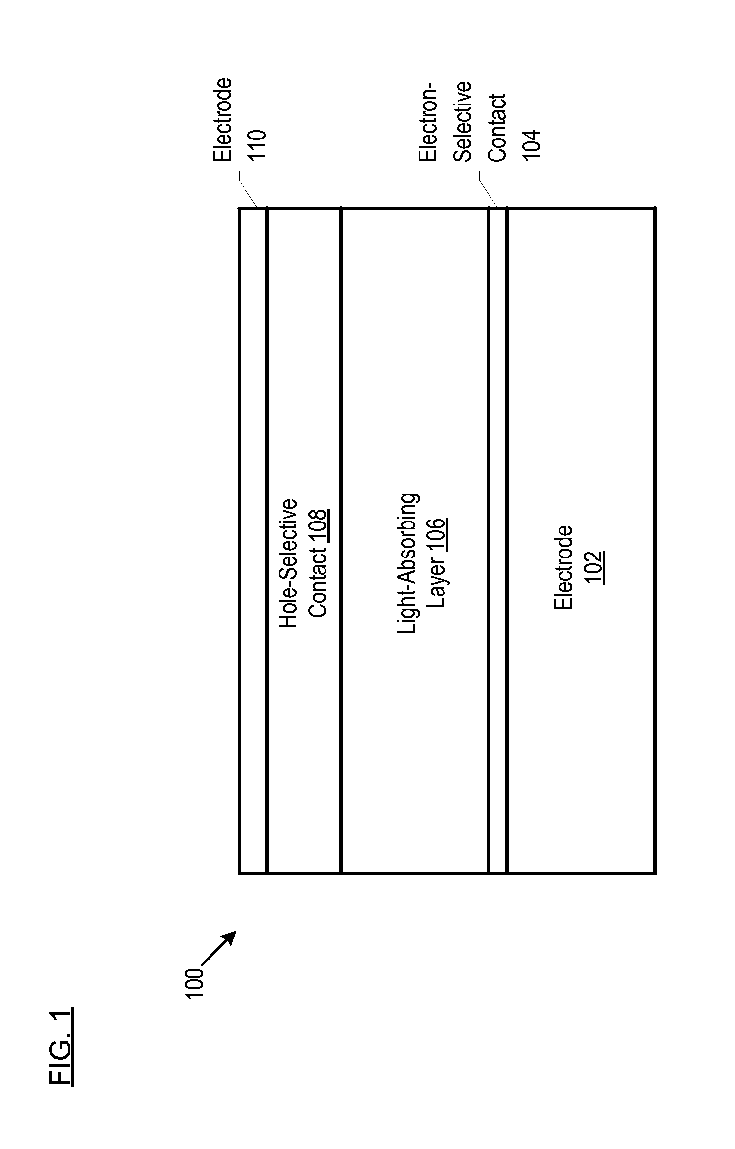
[0083]An FTO-coated glass slide (15 Ωsq−1) served as a substrate and transparent electrode (FIG. 1: electrode 102). FTO was removed from one edge of the glass slide by appropriately masking the slide and etching with Zn powder and 2 M HCL. (This was to avoid a shunt pathway upon contacting the finished device with the anode.) The etched substrate was cleaned, sequentially, with Extran® brand detergent (commercially available from EMD Millipore, a division of Merck KGaA, headquartered in Billerica, Mass.), acetone, isopropanol, and oxygen plasma.

[0084]A layer of TiO2 (serving as electron-selective contact 104) was deposited by spray pyrolysis. Titanium diisopropoxide bis(actylacetonate) (3.0 mL, 6.2 mmol) was diluted in ethanol (27 mL) and sprayed onto the FTO-coated glass, which was maintained at 500° C. The nascent device was then cooled to room temperature, heated at 70° C. for 0.5 hours in a 0.04 M aqueous solution of TiCl4, and then washed in de...


PUM

PropertyMeasurementUnit
transparentaaaaaaaaaa
band gapaaaaaaaaaa

Abstract

A solar cell includes a light-absorbing layer comprising a 2d-perovskite.

Description

[0001]This case claims priority to U.S. Pat. Appl. No. 62 / 008,704 filed on Jun. 6, 2014 and which is incorporated by reference herein.FIELD OF THE INVENTION[0002]The present invention relates generally to solar cells.BACKGROUND OF THE INVENTION[0003]Pressure to use renewable energy sources is growing. One renewable energy source is the sun. Energy from the sun can be harvested by converting sunlight to electricity using a photovoltaic cell or a photoelectrochemical cell. Both such cells are commonly known as “solar cells.”[0004]A basic photovoltaic cell includes a light-absorbing region bounded on one side by a hole-selective contact and on the other side by an electron-selective contact. When sunlight shines on a photovoltaic cell, it can be reflected, absorbed, or transmitted. Only the light that is absorbed in the light-absorbing region ultimately generates electricity. More particularly, only photons having an energy that is at least equal to the band gap of the light-absorbing ...

Claims


Application Information

Patent Timeline
Patent Type & Authority Applications(United States)
IPC IPC(8): H01L51/42H01L51/00H01L51/44
CPCH01L51/4253H01L51/445H01L51/005H01L51/0003H01L2251/305H01L51/442Y02E10/549H10K71/12H10K85/00H10K30/151H10K85/50H01L31/0256Y02E10/50H10K30/30H10K85/20H10K30/82
Inventor KARUNADASA, HEMAMALA INDIVARISMITH, IANMCGEHEE, MICHAEL DAVID
Owner THE BOARD OF TRUSTEES OF THE LELAND STANFORD JUNIOR UNIV
Why Eureka
Try Eureka