Radio Frequency Process Sensing, Control, And Diagnostics Network

a technology of process sensing and control, applied in the direction of transmission monitoring, electrical control, machines/engines, etc., can solve the problems of time delay, additional variability, and inability to optimize or detect processes efficiently, and achieve the effect of optimizing the process

Active Publication Date: 2015-12-10
CTS CORP ELKHART
View PDF5 Cites 39 Cited by
  • Summary
  • Abstract
  • Description
  • Claims
  • Application Information

AI Technical Summary

Benefits of technology

[0014]A sensing and control system and method is disclosed, which utilizes cavity resonance and waveguide measurements to directly monitor process state variables or detect changes in the state of a system and provide direct in situ feedback control to optimize the process. The same system may be used to monitor a number of different process parameters including the composition, amount, distribution, and physical or chemical properties of a material, or to monitor the state or health of a system or sub-system, by monitoring the changes in the dielectric properties of the cavity or waveguide. The system is broadly applicable to wide range of systems and process ranging from engines and exhaust systems to production plants.

Problems solved by technology

First, in many systems there is a need to physically remove a sample from a discrete point in the system at specified time intervals in order to subsequently analyze the sample. These measurements incur a time delay between the time when the sample is collected and when the sample is analyzed, which may range from a few minutes to weeks or even months in some cases. The process of removing the sample may introduce additional variability in the measurements, which may be related to sample handling, the sampling method employed, and the location and timing of the sample extraction, among others. In addition to introducing potential for added variability, measurements based on extracted samples provide limited information corresponding only to the sample characteristics or state at the time of sample extraction from the system. The time delay between sample collection and receipt of measurement results does not allow for efficient process optimization or detection of faults or error conditions when they occur.
Second, many processes employ sensors to monitor the state or characteristics of various system parameters in-line. Examples of these types of sensors include temperature sensors, pressure sensors, moisture sensors, composition sensors such as gas sensors, particle sensors, and similar sensors. Most of these sensors, however, only provide a measurement of the process parameters in close proximity to the sensor or require close contact between the material being measured and the sensing element itself. Use of these types of sensors greatly restricts the type of parameters which may be directly monitored, and also limits the measurements to discrete points in the system where the sensors are located.
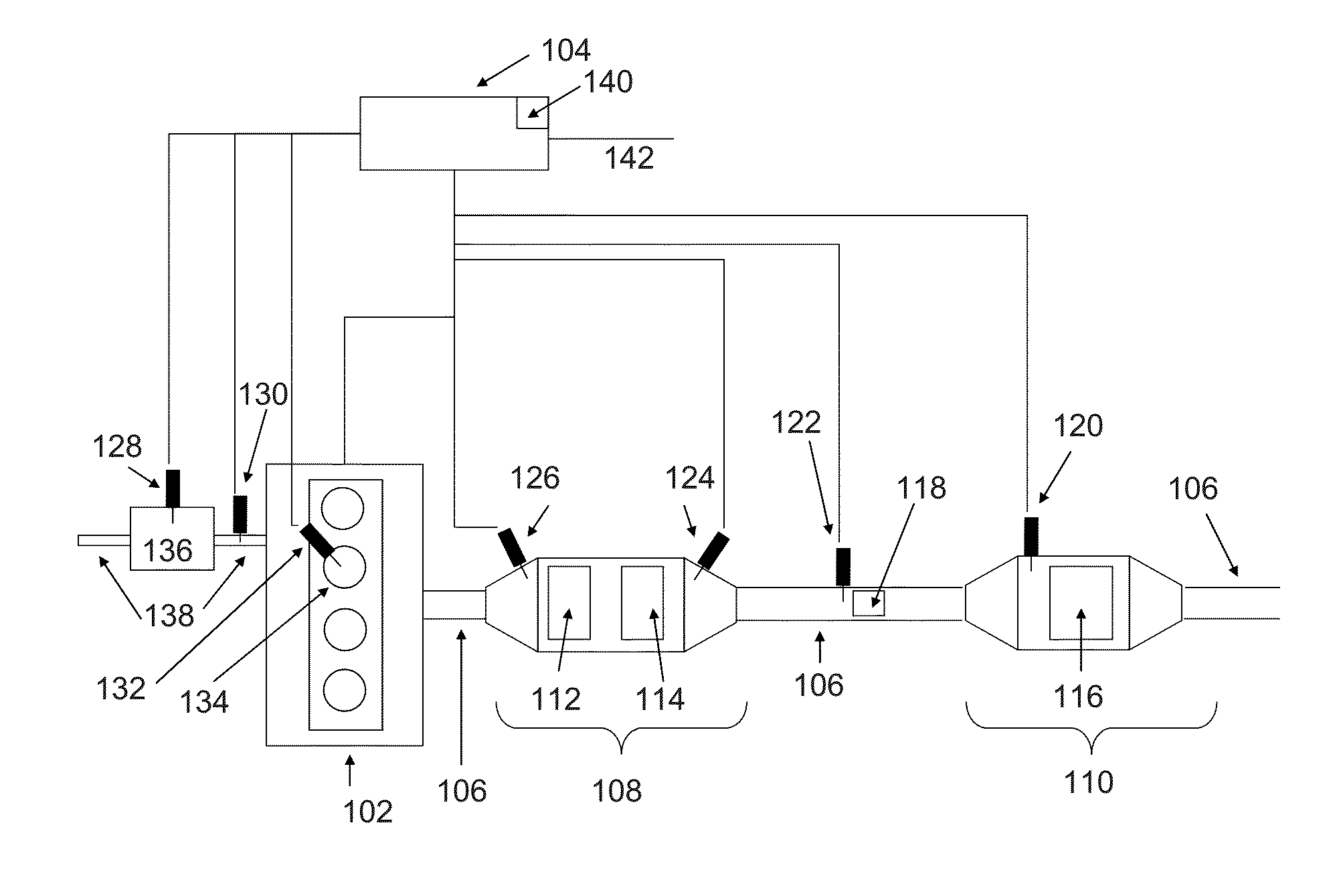
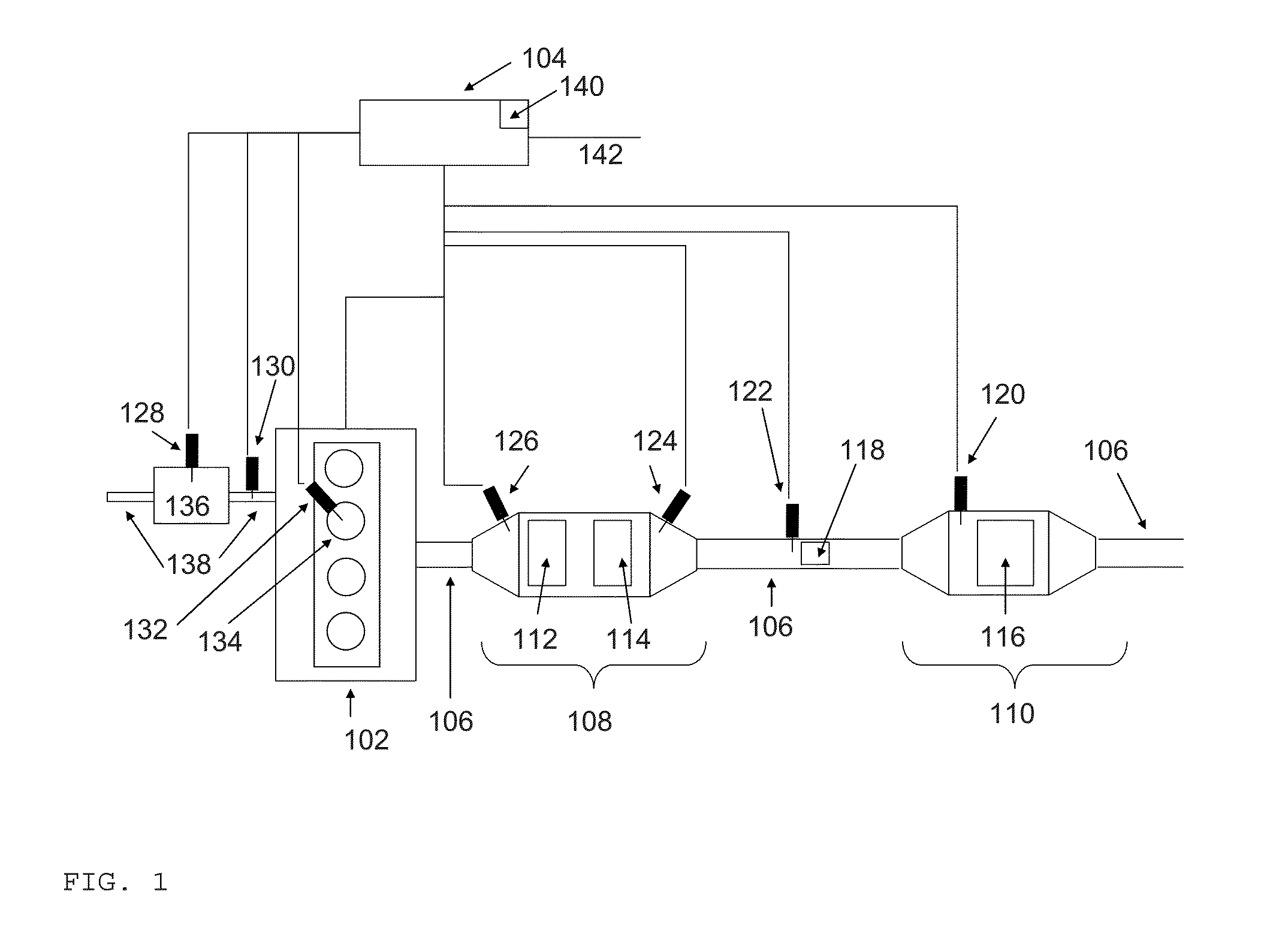
Third, in order to measure various different characteristics of a system, many different types of sensors are generally required, each employing a different measurement principle. For example, temperature, pressure, and gas composition sensors (oxygen, NOx, ammonia, PM) may be used in an exhaust system. Use of many different types of sensors, each with their own specific requirements and response characteristics, increases the cost and complexity of sensing and control networks.
Fourth, despite the prevalence of a large number of sensors, oftentimes the actual state variable of interest may not be measured directly, and must be indirectly estimated based on measurements from available sensors. For example, the amount of material accumulated on a filter may be inferred from pressure drop measurements across the filter, or the amount of a gas adsorbed on a catalyst may be inferred from gas composition sensors monitoring gas composition upstream or downstream of the catalyst. In another example, measurements of upstream and downstream process parameters may be used to infer or indirectly detect a failure of malfunction of a device, such as a filter or catalyst, using conventional sensors. However, in these cases, direct measurement of the required state variable, namely the amount of material on the filter or the quantity of a species adsorbed on a catalyst can not be measured directly. Such indirect estimates suffer from poor accuracy, and are cumbersome and time-consuming to calibrate.
Fifth, in many cases, there is a need to detect system faults or malfunctions when they occur, or preferentially to detect signs of faults or malfunctions before they occur. In particular, certain components in the system may mask signs of faults or malfunctions making them difficult to detect through conventional sensing means. For example, exhaust particulate filters may mask observable signs of impending engine faults, such as smoke related to high oil or fuel consumption or water vapor due to a coolant leak. Such faults are difficult to detect using conventional sensors, or may be easily mistaken or confused, using measurements from conventional sensors.
Such sensors suffer from fouling, poisoning, or aging through the build-up of contaminant material on the sensing element, which needs to be avoided.

Method used


Image

  • Radio Frequency Process Sensing, Control, And Diagnostics Network
  • Radio Frequency Process Sensing, Control, And Diagnostics Network
  • Radio Frequency Process Sensing, Control, And Diagnostics Network

Examples


Embodiment Construction

[0018]FIG. 1 depicts a plant such as an engine and exhaust system monitored by a radio frequency system. The plant may be any type of plant, such as a chemical plant, food processing plant, power plant, refinery, distillery, or any type of plant or process. The plant or reactor may be a flowing reactor, or it could be a batch reactor.

[0019]A machine 102, such as an engine in one example or a plant in another example, may have outlet connection, such as a conduit 106, which may be connected to various components and sensors. Machine 102 may generate an output stream, such as an exhaust stream, or any other stream, which may or may not be directed through conduit 106. In one embodiment, conduit 106 may be connected to a first module 108 and a second module 110. In one embodiment, modules 108 and 110 may be cavities, such as resonant cavities, or may be waveguides in another embodiment.

[0020]In a particular embodiment, module 108 may be particulate filter housing, such as a gasoline pa...


PUM


Abstract

A sensing and control system and method is disclosed, which utilizes cavity resonance and waveguide measurements to directly monitor process state variables or detect changes in the state of a system and provide direct in situ feedback control top optimize the process. The same system may be used to monitor a number of different process parameters including the composition, amount, distribution, and physical or chemical properties of a material, or to monitor the state or health of a system or sub-system. The system is broadly applicable to wide range of systems and process including ranging from engines and exhaust systems to production plants.

Description

[0001]This application claims priority of U.S. Provisional Patent Application Ser. No. 62 / 008,505, filed Jun. 6, 2014, the disclosure of which is incorporated herein by reference in its entirety.BACKGROUND OF THE INVENTION[0002]Radio frequency measurements utilizing cavities and waveguides may be used in a wide range of process control systems, to monitor the state of the system, detect faults, and provide adaptive feedback control to optimize the process. Microwave cavity and waveguide measurements are useful to provide information on the state of the system in situ, without the need for sample removal and subsequent analysis, as is the case with many existing systems.[0003]Examples to illustrate the broad applicability of radio frequency-based cavity and transmission measurement systems include: engines and engine systems, power plants, chemical plants, petroleum extraction and processing, and process sensing and controls in any number of systems.[0004]Current sensing and control ...

Claims


Application Information

Patent Timeline
Patent Type & Authority Applications(United States)
IPC IPC(8): H04B17/00
CPCH04B17/00F02D41/0235F01N2560/026F01N2900/1402F01N2560/12F01N11/00F01N2560/021F01N2550/02F01N2550/04F02D41/1444Y02T10/40H04B17/309
Inventor SAPPOK, ALEXANDERBROMBERG, LESLIE
Owner CTS CORP ELKHART
Why Eureka
Try Eureka