
Distillate two-phase hydrogenation reactor and hydrogenation method

a hydrogenation reactor and two-phase technology, applied in the direction of hydrocarbon oil treatment products, metal/metal-oxide/metal-hydroxide catalysts, physical/chemical process catalysts, etc., can solve the problems of reducing the hydrogenation efficiency of the circulating hydrogen compressor, reducing the amount of high-grade feedstock oil, and high investment and operation costs of the hydrogenation compressor. achieve the effect of improving the hydrogenation efficiency and the applicability of raw materials

Active Publication Date: 2015-12-17
PETROCHINA CO LTD
View PDF5 Cites 0 Cited by
  • Summary
  • Abstract
  • Description
  • Claims
  • Application Information

AI Technical Summary

Benefits of technology

The present invention provides a distillate two-phase hydrogenation reactor and a hydrogenation method that can effectively supplement the hydrogen gas in the liquid-phase raw material, remove harmful impurities, and improve hydrogenation efficiency and raw material applicability. The reactor has a suitable structure that prevents flooding and blocking of gas lines, and uses a stripping component to reduce the adverse effect of impurities after reaction on the next step of the reaction. The liquid-phase hydrogenation method introduces the liquid-phase material supplemented with dissolved hydrogen into the next hydrogenation catalyst bed, while adding gas-phase hydrogen into the catalyst bed to form a gas-liquid countercurrent and increase the concentration of hydrogen gas on the catalyst bed, improving reaction efficiency and stripping hydrogen sulfide and ammonia produced impurities.

Problems solved by technology

However, the supply amount of high-grade feedstock oil has been decreasing.
How to utilize the low-grade feedstock oil to manufacture diesel with ultralow sulfur content to meet the increasing demand has been a big challenge that the refineries have to face.
As key equipment for the hydrogenation process, the circulating hydrogen compressor has a high cost in investment and operation.
However, this liquid-phase circulation hydrogenation process also has one problem, that is, in order to meet the hydrogen gas volume needed in the hydrogenation reaction, it is necessary to use a large amount of circulation oil or additionally add a solvent to dissolve the hydrogen gas, which results in the reduction of the hydrogenation efficiency.
In order to control the reaction temperature of a catalyst bed and prevent the catalyst from deactivation by carbon deposition, generally a high hydrogen-oil volume ratio is used, which certainly causes a large amount of surplus hydrogen gas after completion of the hydrogenation reaction.
For this process, the investment of the circulating hydrogen compressor occupies a relatively high proportion of the whole hydrogenation device cost.
It is generally considered that the increase in the flow rate of the liquid enhances the wetting effect of the catalyst, while the conventional hydrogenation process mostly utilizes a high ratio of hydrogen to oil much more than the need of the reaction, thereby decreasing the wetting effect of the catalyst, and having an adverse influence on the wetting factors.
In addition, the investment of the section of hydrogen circulation during petroleum refining occupies a large proportion of the cost of the whole process.
However, it needs to utilize a solvent or diluent with a high hydrogen solubility to dissolve hydrogen, which influences the subsequent hydrogenation efficiency.
But these patents have not totally resolved the problem of removing the detrimental impurity such as H2S and NH3 produced in the hydrorefining reaction process, which results in a continueous accumulation of these impurities in the reactor, thereby greatly reducing the reaction efficiency, and failing to effectively handle raw material with high sulphur and nitrogen content.
The above patents do not disclose the specific structure of the reactor, either.

Method used


Image

  • Distillate two-phase hydrogenation reactor and hydrogenation method
  • Distillate two-phase hydrogenation reactor and hydrogenation method
  • Distillate two-phase hydrogenation reactor and hydrogenation method

Examples


example 1

[0032]The mixed diesel oil was sufficiently mixed with hydrogen gas for dissolving hydrogen, and then introduced into the hydrogenation reactor under the reaction conditions of the hydrogen partial pressure at 6.0 MPa, the reaction temperature at 311° C., and the amount of hydrogen gas supplemented among the catalyst beds being 1:1 in terms of hydrogen-oil volume ratio. A portion of the liquid-phase product passed through the circulation pump as the circulated oil, and was mixed with fresh raw material for dissolving hydrogen, and then introduced into the reactor, and another portion of the liquid-phase product was introduced into the product tank in the form of product. The properties of the feedstock oil and the properties of the products are listed in Table 2.

[0033]As seen from Table 2, the sulfur and nitrogen content in the diesel oil can be reduced remarkably by the use of this technology.

example 2

[0034]The heavy gatch feedstock was sufficiently mixed with hydrogen gas for dissolving hydrogen, and then introduced into the hydrogenation reactor under the reaction conditions of the hydrogen partial pressure at 12.0 MPa, the reaction temperature at 370° C., and the amount of hydrogen gas supplemented among the catalyst beds being 3:1 in terms of hydrogen-oil volume ratio. A portion of the liquid-phase product passed through the circulation pump as the circulated oil, and was mixed with fresh raw material for dissolving hydrogen, and then introduced into the reactor, and another portion of the liquid-phase product was introduced into the product tank in the form of product. The properties of the feedstock oil and the properties of the products are listed in Table 3.

[0035]As seen from Table 3, when the mixed gatch containing 10 wt % coker gatch is used as the raw material, the content of sulfur and nitrogen impurities in the heavy gatch can be reduced remarkably by the use of this...

example 3

[0036]The gatch feedstock processed by Example 2 was sufficiently mixed with hydrogen gas for dissolving hydrogen, and then introduced into the hydrogenation reactor under the reaction conditions of the hydrogen partial pressure at 12.0 MPa, the reaction temperature at 385° C., and the amount of hydrogen gas supplemented among the catalyst beds being 7:1 in terms of hydrogen-oil volume ratio. A portion of the liquid-phase product passed through the circulation pump as the circulated oil, and was mixed with fresh raw material for dissolving hydrogen, and then introduced into the reactor, and another portion of the liquid-phase product was introduced into the product tank in the form of product, and then cut according to the true boiling point. The properties of the feedstock oil are listed in Table 4, and the product distribution and properties are listed in Table 5.

[0037]As seen from Table 5, when the mixed gatch containing 10 wt % coker gatch is used as the raw material, under the ...


PUM

PropertyMeasurementUnit
temperatureaaaaaaaaaa

Abstract

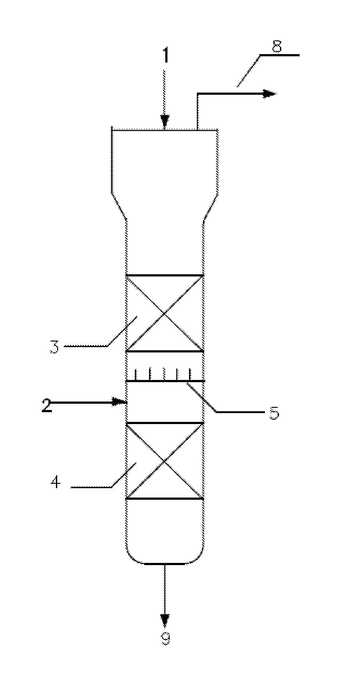
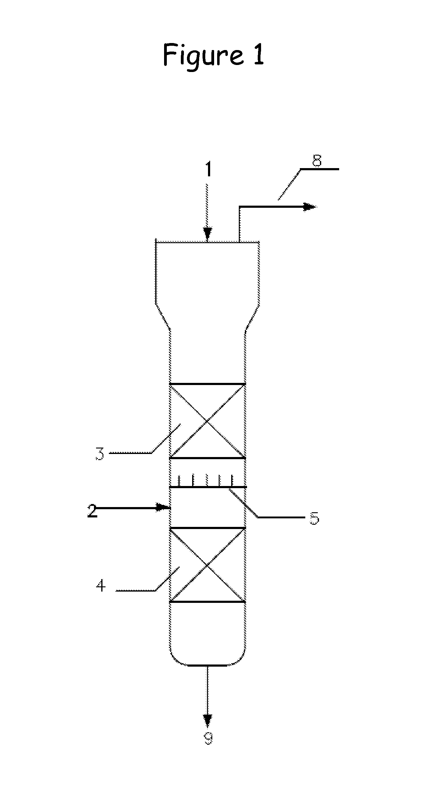
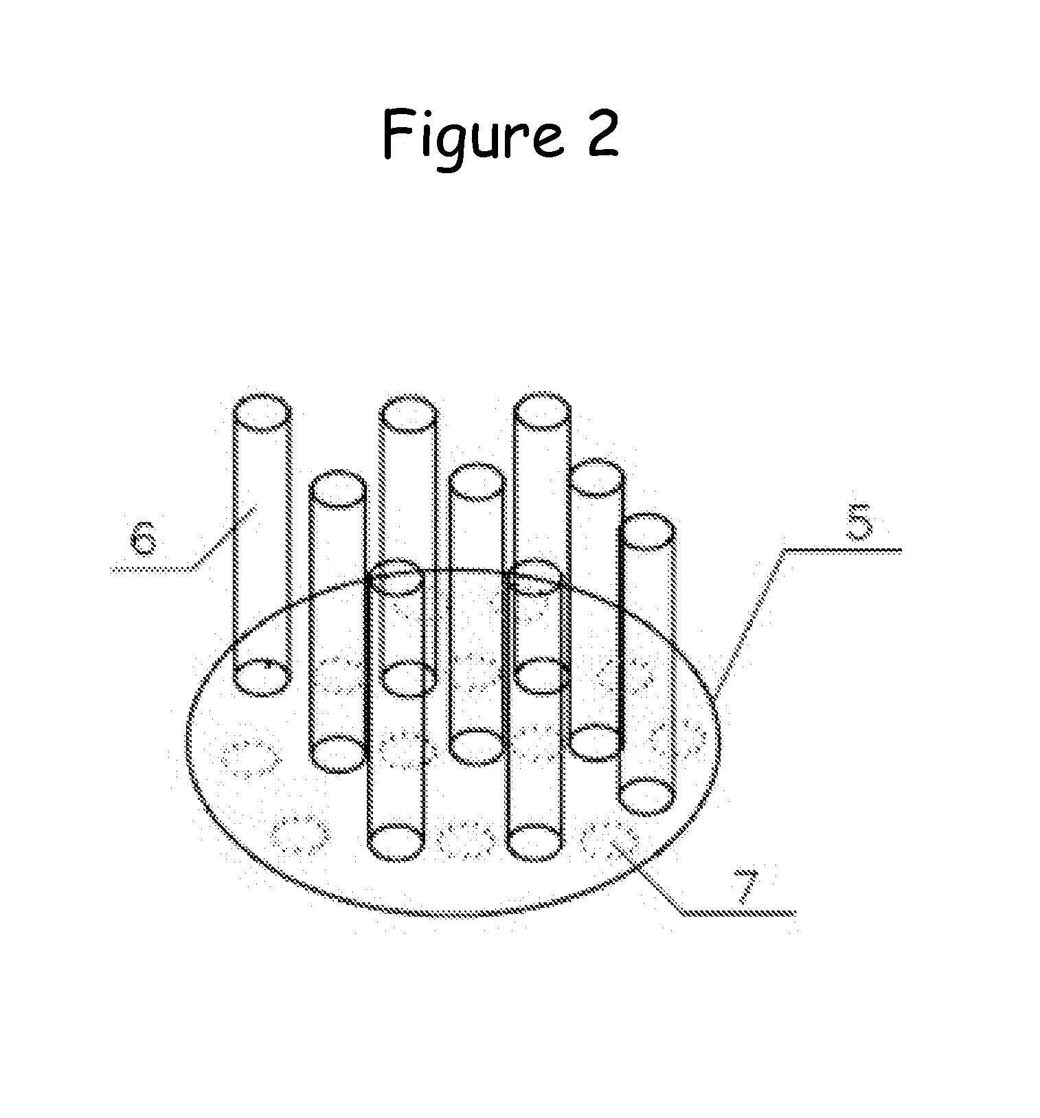
A hydrogenation method and distillate two-phase hydrogenation reactor in which the size of an upper space of the reactor is greater than that of a lower catalyst bed part. The reactor comprises 2 to 4 catalyst beds. An inner component for gas replenishment and for stripping a liquid-phase stream containing impurities is arranged between at least one adjacent catalyst bed and comprises a separator plate and exhaust pipes. The separator plate is provided with multiple downcomer through holes. The separator plate is connected with a plurality of exhaust pipes. The exhaust pipes are vertically arranged above the separator plate. The top parts of the exhaust pipes are in contact with the lower part of the upper catalyst bed.

Description

FIELD OF THE INVENTION[0001]The present invention relates to a distillate two-phase hydrogenation reactor and a hydrogenation method, specifically to a liquid phase reactor with product circulation, especially a reactor with circulating a product containing dissolved hydrogen gas in hydrocarbon liquid-phase material and liquid-phase hydrogenation, and a liquid-phase hydrogenation method using the reactor.BACKGROUND OF ART[0002]With increasingly reinforced environmental consciousness, many countries have limited sulfur content of diesel fuel to a quite low level (10 to 15 μg / g), to reduce the emission of harmful gases, and improve air quality by means of environmental legislation. The sulfur content of diesel fuel was decreased to 15 μg / g in 2006 in USA. The sulfur content of diesel fuel was decreased to 10 μg / g in January, 2003 in Germany. The sulfur content of diesel fuel was decreased to 10 μg / g in 2008 in other countries of European Union (EU) and Japan. The national standard on ...

Claims


Application Information

Patent Timeline
Patent Type & Authority Applications(United States)
IPC IPC(8): C10G65/08C10L1/08
CPCC10G65/08C10L2290/545C10L2270/026C10L1/08B01J8/0453B01J8/0492B01J2208/00849B01J2208/00938C10G45/20C10G65/04C10G2400/02C10G2400/04C10G2400/08C10G2400/10C10L1/04
Inventor MA, SHOUTAOTIAN, RANZHANG, ZHIHUAWANG, GANGSUN, FAMINZHANG, RUIQINYU, CHUNMEISUN, SHENGBOFENG, XIUFANGLI, FENGXUANZHU, JINLING
Owner PETROCHINA CO LTD
Learn More