Eureka AIR delivers breakthrough ideas for toughest innovation challenges, trusted by R&D personnel around the world.

Organic electroluminescent element and lighting device

a technology of electroluminescent elements and lighting devices, applied in the direction of organic semiconductor devices, thermoelectric devices, solid-state devices, etc., can solve the problems of poor gas barrier properties, deterioration of electron devices, water vapor and oxygen permeation into the substrate, etc., to suppress the occurrence of short-circuits, suppress the deterioration of storage properties, and improve light emission efficiency

Inactive Publication Date: 2015-12-31
KONICA MINOLTA INC
View PDF3 Cites 11 Cited by
  • Summary
  • Abstract
  • Description
  • Claims
  • Application Information

AI Technical Summary

Benefits of technology

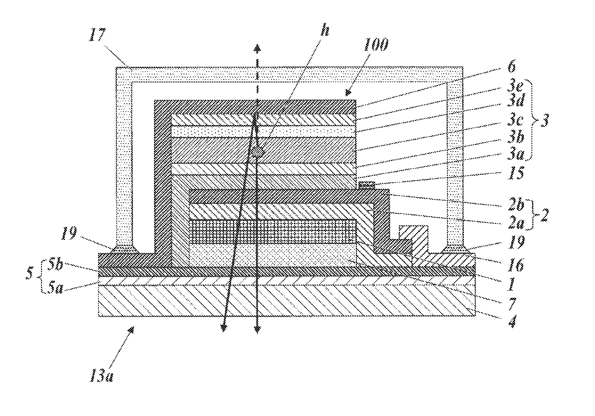
The present invention provides an organic electroluminescent element that has improved light emitting efficiency and suppressed deterioration under high temperature-high humidity atmospheres. This is achieved by providing a smooth layer with controlled surface roughness that prevents defects such as short-circuit and improves the overall performance of the element.

Problems solved by technology

However, film substrates such as transparent plastics have problems that they have poorer gas barrier properties than those of glass substrates.
It has been clarified that, when a substrate having a poor gas barrier property is used, there is a problem that water vapor and oxygen permeate into the substrate and deteriorate the functions in an electron device, or the like.
However, there are problems that recess-projection is formed on the surface by forming a gas barrier layer and a light scattering layer on a film substrate, and that deterioration of the storage property under a high temperature-high humidity atmosphere and short-circuit (electrical short-circuit) easily occur by forming a light emitting unit having an organic functional layer on the upper layer thereof.

Method used


Image

  • Organic electroluminescent element and lighting device
  • Organic electroluminescent element and lighting device
  • Organic electroluminescent element and lighting device

Examples


example 1

Light emitting panel No. 1

Comparative Example

Preparation of Sample

(1) Preparation of Film Substrate and Gas Barrier Layer

[0431](1-1) Film Substrate

[0432]As a film substrate, a biaxially-stretched polyethylene naphthalate film (a PEN film, thickness: 100 μm, width: 350 mm, manufactured by Teijin DuPont Films Japan Limited, commercial product name “Teonex Q65FA”) was used.

[0433](1-2) Preparation of Primer Layer

[0434]A UV curable organic-inorganic hybrid hard coat material OPSTAR Z7501 manufactured by JSR Corporation was applied with a wire bar onto an easily-adhesive surface of a film substrate so that the dry layer thickness became 4 μm, dried under drying conditions; 80° C. and 3 min, and cured under an air atmosphere by using a high pressure mercury lamp at a curing condition; 1.0 J / cm2, whereby a primer layer (also referred to as “primer layer”) was formed.

[0435]The maximum cross-sectional surface height Ra (p) that represents the surface roughness at that time was 5 nm.

[0436]The...

example

(1) Preparation of Film Substrate and Gas Barrier Layer

[0585]With respect to light emitting panel No. 10, the preparation steps of (1-1) to (1-4) for light emitting panel No. 2 were similarly conducted by using a similar film substrate to that for light emitting panel No. 2.

(2) Preparation of Light Scattering Layer and Smooth Layer

[0586](2-1) Preparation of light scattering layer

[0587]As a substrate, a substrate obtained by cutting the film substrate obtained in (1) into 50×50 mm, washing with ultrapure water and drying with a clean drier was used.

[0588]Subsequently, a light scattering layer preparation liquid was formulated and designed at a ratio of 10 ml amount so that the solid content ratio of TiO2 particles having a refractive index (np) of 2.4 and an average particle diameter of 0.5 μm (JR600A manufactured by TAYCA CORPORATION) to a resin solution (ED230AL (an organic-inorganic hybrid resin) manufactured by APM) became 30 vol % / 70 vol %, the solvent ratio of n-propylacetate t...

example 2

(6) Evaluations

[0634]The following evaluations were conducted by using the obtained light emitting panels (lighting devices) Nos. 1 to 13.

[0635](6-1) Total Luminous Flux

[0636]A luminous flux at a predetermined electrical current was measured by using an integrating sphere. Specifically, a total luminous flux was measured at a constant electrical current density of 20 A / m2, and a relative value with respect to light emitting panel No. 2 was shown in Table 2.

[0637](6-2) Storage Property Test Under High Temperature-High Humidity Atmosphere

[0638]The obtained light emitting panels Nos. 1 to 13 were each stored under an atmosphere at a temperature of 60° C. / a relative humidity of 90% RH, and the light emitting state was observed. Specifically, the progress of the decrease of the light emitting surface area (shrink) after 500 hours compared to the light emitting surface area before the initiation of the test was observed, and the result was shown in Table 2. The case when 100 μm or more of...


PUM


Abstract

An object of the present invention is to provide an organic electroluminescent element, which has a light emitting efficiency improved by suppressing the deterioration of storage property under a high temperature-high humidity atmosphere due to the recess-projection state of a surface of a gas barrier layer or a light scattering layer, or the like that is in contact with a light emitting unit, and by suppressing the occurrence of a short-circuit. The organic electroluminescent elements 100 and 400 in the present invention are each characterized by including a film substrate 4, and at least, a gas barrier layer 5, a smooth layer 1, and a light emitting unit 3 that is sandwiched between a pair of electrodes 2, 6 and has an organic functional layer, which are stacked in this order on the film substrate, wherein the gas barrier layer 5 is constituted by at least two kinds of gas barrier layers 5 that are different from each other in the composition or distribution state of the constitutional elements.

Description

TECHNICAL FIELD[0001]The present invention relates to an organic electroluminescent element. Furthermore, the present invention relates to a lighting device including said organic electroluminescent element. More specifically, the present invention relates to an organic electroluminescent element and a lighting device each having an improved light extraction efficiency.BACKGROUND ART[0002]In recent years, in the field of electron devices, demands such as long term reliability, degree of freedom of forming and possibility of display on a curved surface have been added in addition to demands such as weight saving and increase in size, and thus film substrates such as transparent plastics are beginning to be adopted instead of glass substrates, which are heavy, easily cracked and difficult to be increased in surface area.[0003]However, film substrates such as transparent plastics have problems that they have poorer gas barrier properties than those of glass substrates.[0004]It has been...

Claims


Application Information

Patent Timeline
Patent Type & Authority Applications(United States)
IPC IPC(8): H01L51/52
CPCH01L51/5253H01L51/5268H01L2251/5392H10K50/854H10K2102/341H10K50/8426H10K50/844
Inventor FURUKAWA, KEIICHIYAGI, TSUKASA
Owner KONICA MINOLTA INC
Why Eureka
Eureka Blog
Learn More