Electric machine with a cooling device, and method for producing said machine

a cooling device and electric machine technology, applied in the direction of cooling/ventilation arrangement, stator/rotor body manufacturing, solid insulation, etc., can solve the problems of reducing the efficiency of the electric machine, damage to the electric machine, and increasing the temperature of the components, so as to reduce the installation space, reduce the thermal resistance, and thin the wall

Inactive Publication Date: 2015-12-31
SCHAEFFLER TECH AG & CO KG
View PDF12 Cites 17 Cited by
  • Summary
  • Abstract
  • Description
  • Claims
  • Application Information

AI Technical Summary

Benefits of technology

[0025]The distance between the cooling medium and the soft-magnetic core or the winding heads can be designed to be considerably smaller than in the case of conventional cooling jackets, as explained above for the state of the art. In injection-molding processes, much thinner walls can be made than in the case of a metal cooling channel that is created separately by machining. On the one hand, these thinner walls reduce the thermal resistance and, on the other hand, they require less installation space for the plastic body, or else, within the available installation space, the stator can be configured to be larger and thus more powerful.
[0026]When the plastic body is injection-molded directly in the form of a plastic jacket, full-surface contact with the rough circumferential surface of the soft-magnetic core can be achieved, so that the heat resistance between the stator and the plastic body can be kept low. In contrast, in the case of an interference fit according to the state of the art, small cavities between the cooling jacket and the stator core can increase the heat resistance.
[0027]When an advantageous cooling channel shape is created by means of an injection-molding process, then, with just a bit of extra work involving the injection mold, a complex structure can be made that has a high surface, for example, a wavy configuration. The contact surface between the cooling jacket and the coolant can thus be augmented in a simple manner. Consequently, this transfer resistance between the heat-conductive plastic and the coolant can also be reduced.

Problems solved by technology

When the windings are energized, in addition to converting electric energy into mechanical energy and vice versa, they generate thermal energy which, as a thermal load, leads to a temperature rise in the components, and this can cause damage to the electric machine and lead to a reduction in its efficiency.
Particularly with hybrid drives, this can diminish the performance of the electric machine.
The production of such a cooling device is labor-intensive since an additional sleeve of a cooling jacket with external flutes has to be provided, or else the inner circumference of the housing has to be provided with such flutes.
The production and assembly of such cooling jackets is labor-intensive and, due to the surface roughness, small cavities that increase the heat transfer resistance are formed between the cooling jacket and the stator.

Method used


Image

  • Electric machine with a cooling device, and method for producing said machine
  • Electric machine with a cooling device, and method for producing said machine

Examples


Embodiment Construction

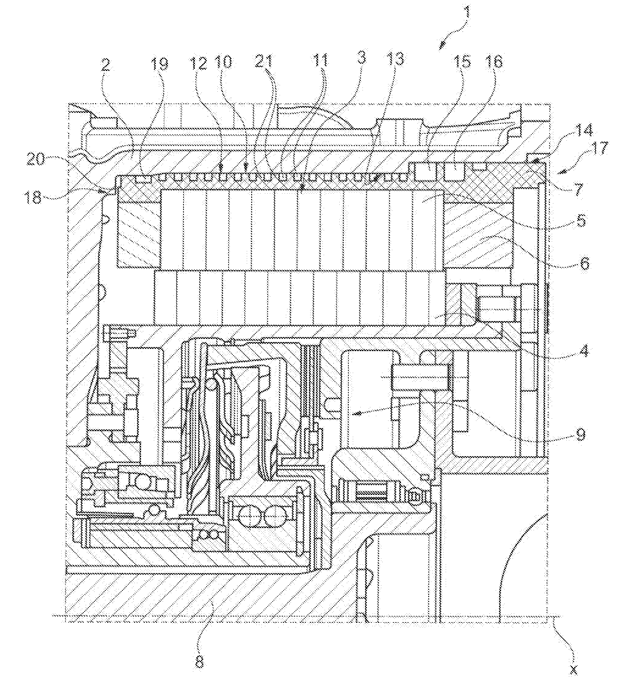
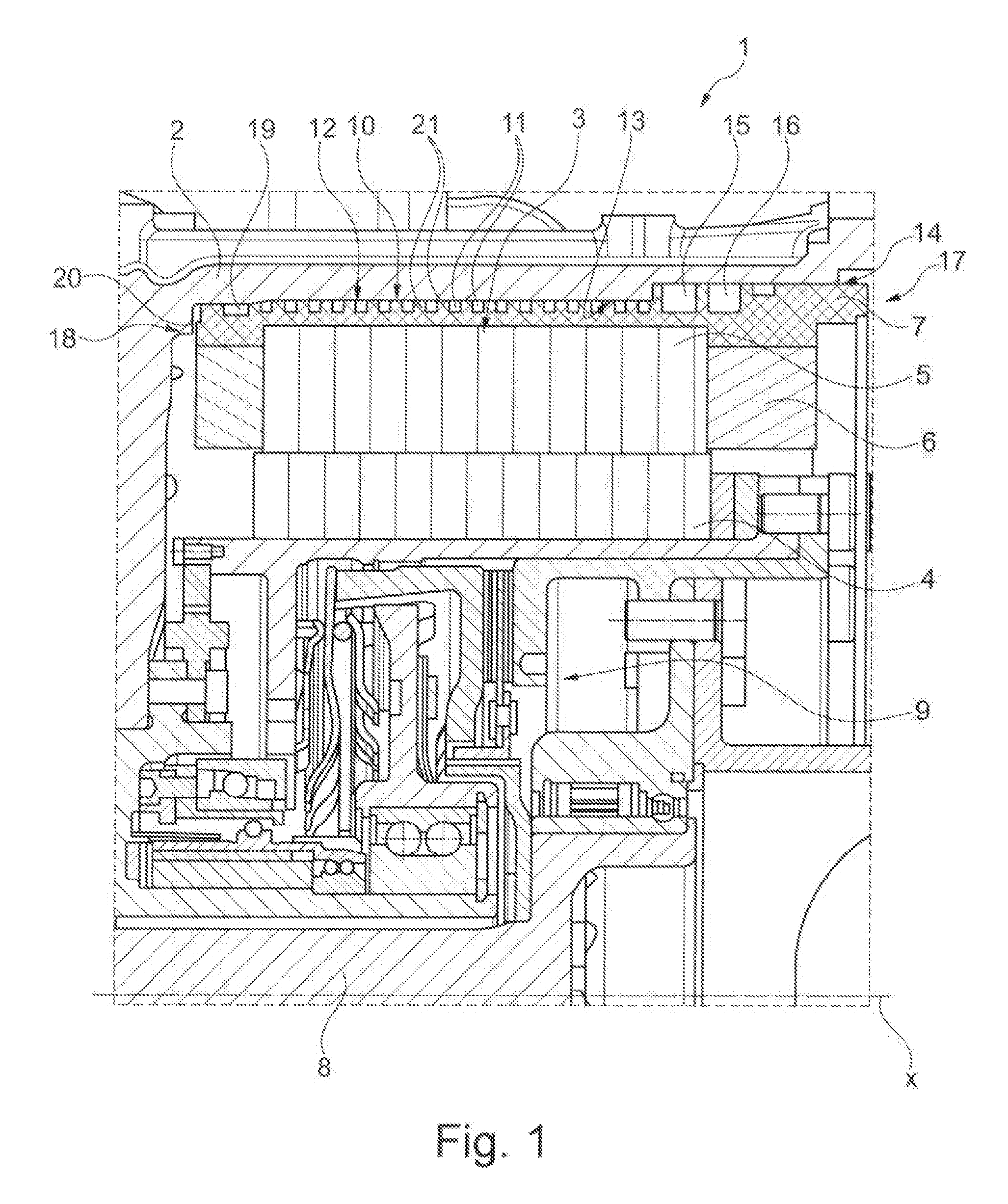
[0029]The single FIGURE shows the electric machine 1 with the housing 2 and the stator 3 that is firmly accommodated in it and, in a partial sectional view, with the rotor 4 that can be rotated around the axis of rotation x. The stator is made up of the soft-magnetic core 5 and of windings with winding heads 6 accommodated in said core 5. The plastic body 7 seals the stator 3 vis-à-vis the housing 2. The friction clutch 9 that is arranged axially inside the rotor 4 is located between the drive shaft 8 and the rotor 4.

[0030]The cooling device 10 is located between the housing 2 and the stator 3. This cooling device 10 is formed by the cooling channel 12 which is created as a recess 11 in the plastic body and in which a coolant is conveyed that dissipates the thermal heat loss from the stator. The recess 11 is arranged in a spiral shape along the axis of rotation x on the outer circumference of the plastic body 7 and it essentially covers the entire axial width of the stator 3. For pu...


PUM


Abstract

An electric machine (1) and to a method for producing the machine (1), including a housing (2) and a stator (3) accommodated therein, as well as at least one rotor (4) arranged radially inside the stator (3), a plastic body (7) that at least radially surrounds the outside of a soft-magnetic core (5) of the stator (3), and a cooling device (10) located between the stator (3) and the housing (2) is provided. In order to improve the cooling device (10), at least one recess (11) that conveys a cooling medium is created between the housing (2) and the stator (3) at least partially in the outer circumferential surface of the plastic body (7).

Description

[0001]The invention relates to an electric machine and to a method for producing said machine, comprising a housing and a stator accommodated therein, as well as at least one rotor arranged radially inside the stator, also a plastic body that at least radially surrounds the outside of a soft-magnetic core of the stator, and a cooling device between the stator and the housing.BACKGROUND[0002]In certain designs, electric machines in the form of electric motors and / or power generators, for example, in drives of motor vehicles, have a stator with a soft-magnetic core and, wound in them or between them, they have windings made of copper wire or copper rods as well as a rotor that is arranged rotatably therein. When the windings are energized, in addition to converting electric energy into mechanical energy and vice versa, they generate thermal energy which, as a thermal load, leads to a temperature rise in the components, and this can cause damage to the electric machine and lead to a re...

Claims


Application Information

Patent Timeline
Patent Type & Authority Applications(United States)
IPC IPC(8): H02K5/20H02K15/02
CPCH02K5/20H02K1/04H02K15/02H02K9/19H02K5/203
Inventor KOBES, MICHAELHOLLAND, MARIAWEBER, ACHIMHILL, WOLFGANG
Owner SCHAEFFLER TECH AG & CO KG
Why Eureka
Try Eureka