Systems and methods for recording simultaneously visible light image and infrared light image from fluorophores
- Summary
- Abstract
- Description
- Claims
- Application Information
AI Technical Summary
Benefits of technology
Problems solved by technology
Method used
Image
Examples
example 1
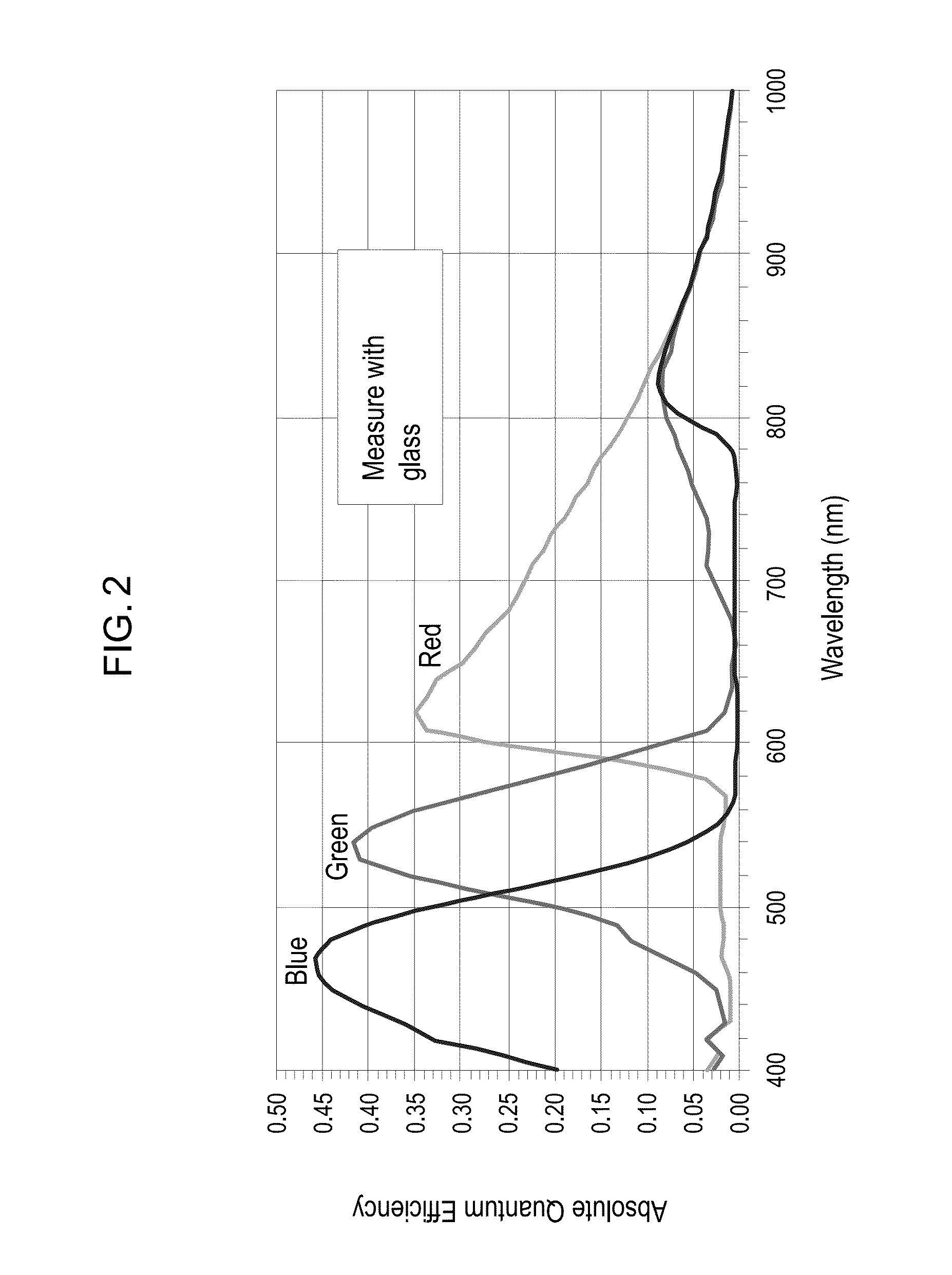
[0163]Charged Coupled Devices (CCDs) or Complementary metal-oxide-semiconductor (CMOS) sensors used in the cameras have a broad spectrum of sensitivity ranging from 400 nm to 1000 nm (FIG. 2). All the Red, Green and Blue sensors show sensitivity in the 800-1000 nm of wavelength. The commercially available cameras have a color filter array (CFA) or color filter mosaic (CFM) as shown in FIG. 3 on top of a sensor to collect color information from the image. In addition to this filter array there is an additional NIR short pass filter to cutoff light from 700-1000 nm of wavelength.
example 2
[0164]We use the sensitivity of Red, Green and Blue pixels in near infrared region (NIR) to detect infrared fluorescence. A visible light source illuminates the sample of interest. Also, a laser is used as the excitation light for the infrared fluorophore in tissue, and the emission light from the infrared fluorophore is detected by a CCD camera. Meanwhile, the excitation light is filtered before reaching the CCD camera to avoid interfering detection of the emission light. An image frame is captured when the laser is on (on-frame). Another image frame is captured when the laser is off (off-frame). The on-frame detects both visible light and infrared fluorescence, while the off-frame detects only visible light. Thus, the difference in the intensity between the on-frame and off-frame provides information about the infrared fluorescence signal. (FIG. 4).
1. Excitation:
[0165]Excitation is achieved using a very narrow wavelength laser @ NIR wavelength (high absorption) 780 or 785 nm. The ...
example 3
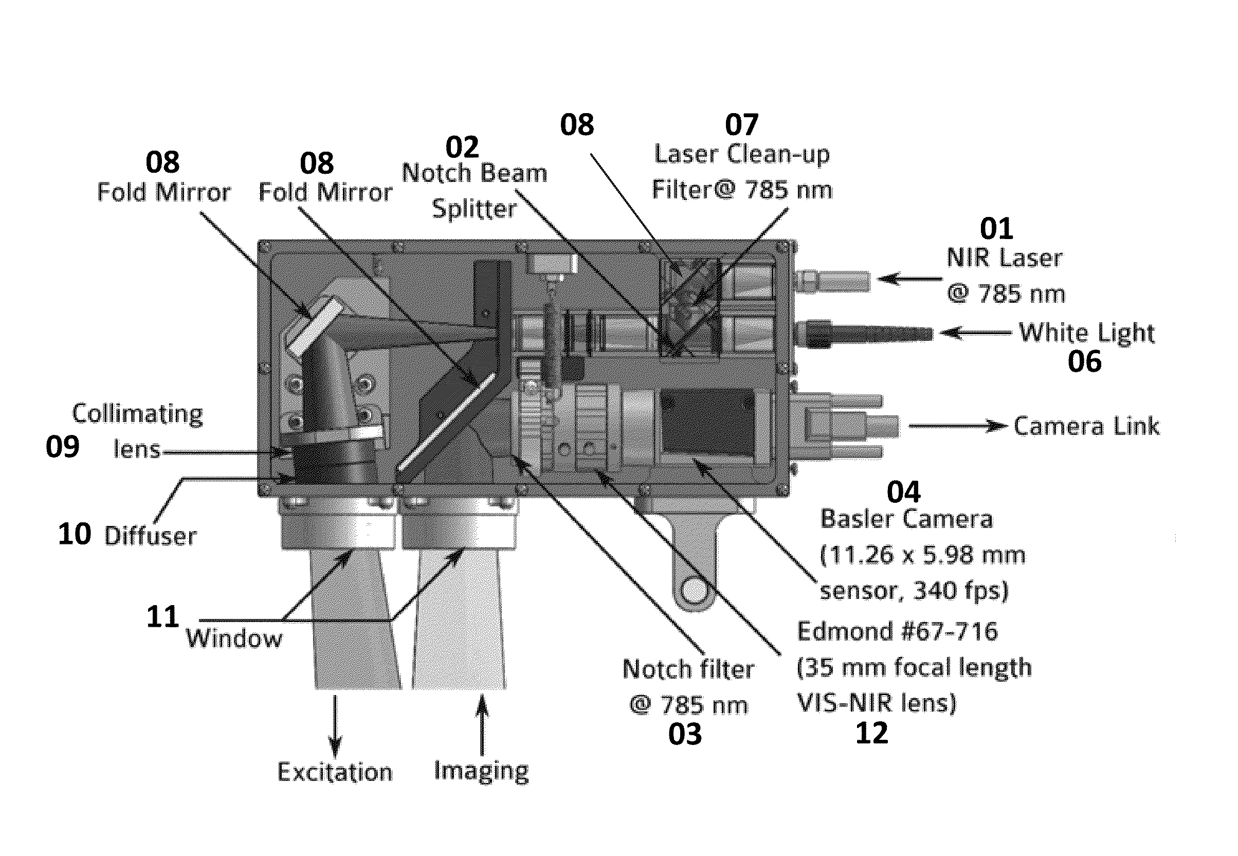
[0168]By removing the NIR short pass filter in front of the sensor, it is possible to detect fluorescence light emitted by the NIR fluorophores on all RGB channels (FIG. 2). But in order to differentiate between the visible light and NIR light we have to ensure that there is no visible light on the sensor when capturing an NIR image frame. In order to capture the NIR light, there should not be any visible light. In some situations, we capture one frame when there is no visible light or NIR light, record the light, and then subtract it from the NIR captured frame. A clinical prototype is shown in FIGS. 6A-6C.
1. Filter Combination:
[0169]We use a very specific filter combination to achieve highest signal to noise ratio (SNR). Instead of using a broadband excitation as described in most current NIR system, we use an extremely narrow band excitation at 785 nm (optimal for ICG, may vary depending on the fluorophore), the excitation is further narrowed using a laser clean up filter (FIG. 7...
PUM
 Abstract
Description
Claims
Application Information
 - R&D
- Intellectual Property
- Life Sciences
- Materials
- Tech Scout
- Unparalleled Data Quality
- Higher Quality Content
- 60% Fewer Hallucinations
Browse by: Latest US Patents, China's latest patents, Technical Efficacy Thesaurus, Application Domain, Technology Topic, Popular Technical Reports.
© 2025 PatSnap. All rights reserved.Legal|Privacy policy|Modern Slavery Act Transparency Statement|Sitemap|About US| Contact US: help@patsnap.com


