Electrolytic cell for metal electrowinning

a technology of electrowinning cells and electrolysis components, applied in the field of electrowinning cells, can solve the problems of short-circuit current flows, achieve optimal electrical resistance, increase conductivity, and high overvoltage

Inactive Publication Date: 2016-01-28
IND DE NORA SPA
View PDF7 Cites 1 Cited by
  • Summary
  • Abstract
  • Description
  • Claims
  • Application Information

AI Technical Summary

Benefits of technology

[0007]Besides a high overvoltage with respect to the anodic discharge of oxygen, the screen is characterised by a sufficiently compact but porous structure, such that it allows the passage of the electrolytic solution without interfering with the ionic conduction between the cathode and the anode. The inventors have surprisingly found that by carrying out the electrolysis with a cell design as described, dendrites that are possibly formed are effectively stopped before they reach the facing anode surface so that their growth is essentially blocked. The high anodic overvoltage characterising the surface of the screen prevents it from working as anode during the normal cell operation, allowing the lines of current to keep on reaching the anode surface undisturbed. On the other hand, should a dendrite grow from the cathode surface, it will be able to proceed only until it gets in contact with the screen. Once the contact takes place, a circuit of first species conductors is closed (cathode / dendrite / screen / anodic bus-bar), so that the dendrite growth towards the anode becomes less advantageous. The possible deposition of metal on the surface of the screen can even increase its conductivity to some extent, making it subject to short-circuit current flows. The resistance of the screen can be calibrated to an optimal value through the selection of construction materials, their dimensioning (for example, pitch and diameter of wires in the case of textile structures, diameter and mesh opening in the case of meshes) or the introduction of more or less conductive inserts. In one embodiment, the screen can be made of carbon fabrics of appropriate thickness. In another embodiment, the screen can consist of a mesh or perforated sheet of a corrosion-resistant metal, for example titanium, provided with a coating catalytically inert towards the oxygen evolution reaction. This can have the advantage of relying on the chemical nature and the thickness of the coating to achieve an optimal electrical resistance, leaving the task of imparting the necessary mechanical features to the mesh or perforated plate. In one embodiment, the catalytically inert coating may be based on tin, for example in the form of oxide. Tin oxides above a certain specific loading (over 5 g / m2, typically around 20 g / m2 or more) have proved particularly suitable for imparting an optimal resistance in the absence of catalytic activity towards the anodic evolution of oxygen. Other suitable materials for achieving a catalytically inert coating include tantalum, niobium and titanium, for example in form of oxides. In one embodiment, the restraint of the short circuit current is achieved by mutually connecting the anode and the porous screen through a calibrated resistor, for example having a resistance of 0.01 to 100 Ω. An appropriate adjustment of the electrical resistance of the screen allows the device to operate by leveraging the advantages of the invention to the maximum extent: a very low resistance could lead to the drainage of an excessive amount of current, which would somehow diminish the overall yield of copper deposition; on the other hand, a certain conductivity of the screen is useful in order to break the “tip effect”—the main cause of the dendrite growth—and disperse the current flow from the dendrite across the plane, avoiding its growth through the openings of the screen and the consequent risk of mechanical interference in the subsequent procedure of cathode extraction. The optimal point of regulation of the electrical resistance of the screen and the optional resistor in series basically depends on the overall cell size and can be easily calculated by a person skilled in the art.
[0008]In one embodiment, the electrowinning cell comprises an additional non-conductive porous separator, positioned between the anode and the screen. This can have the advantage of interposing an ionic conductor between two planar conductors of the first species, establishing a clear separation between the current flow associated to the anode and the one drained by the screen. The non-conductive separator may be a web of insulating material, a mesh of plastic material, an assembly of spacers or a combination of the above elements. In the case of anodes placed inside an envelope consisting of a permeable separator, as described in concurrent patent application WO2013060786, such role can also be carried out by the same separator.

Problems solved by technology

The possible deposition of metal on the surface of the screen can even increase its conductivity to some extent, making it subject to short-circuit current flows.

Method used


Image

  • Electrolytic cell for metal electrowinning
  • Electrolytic cell for metal electrowinning

Examples


Embodiment Construction

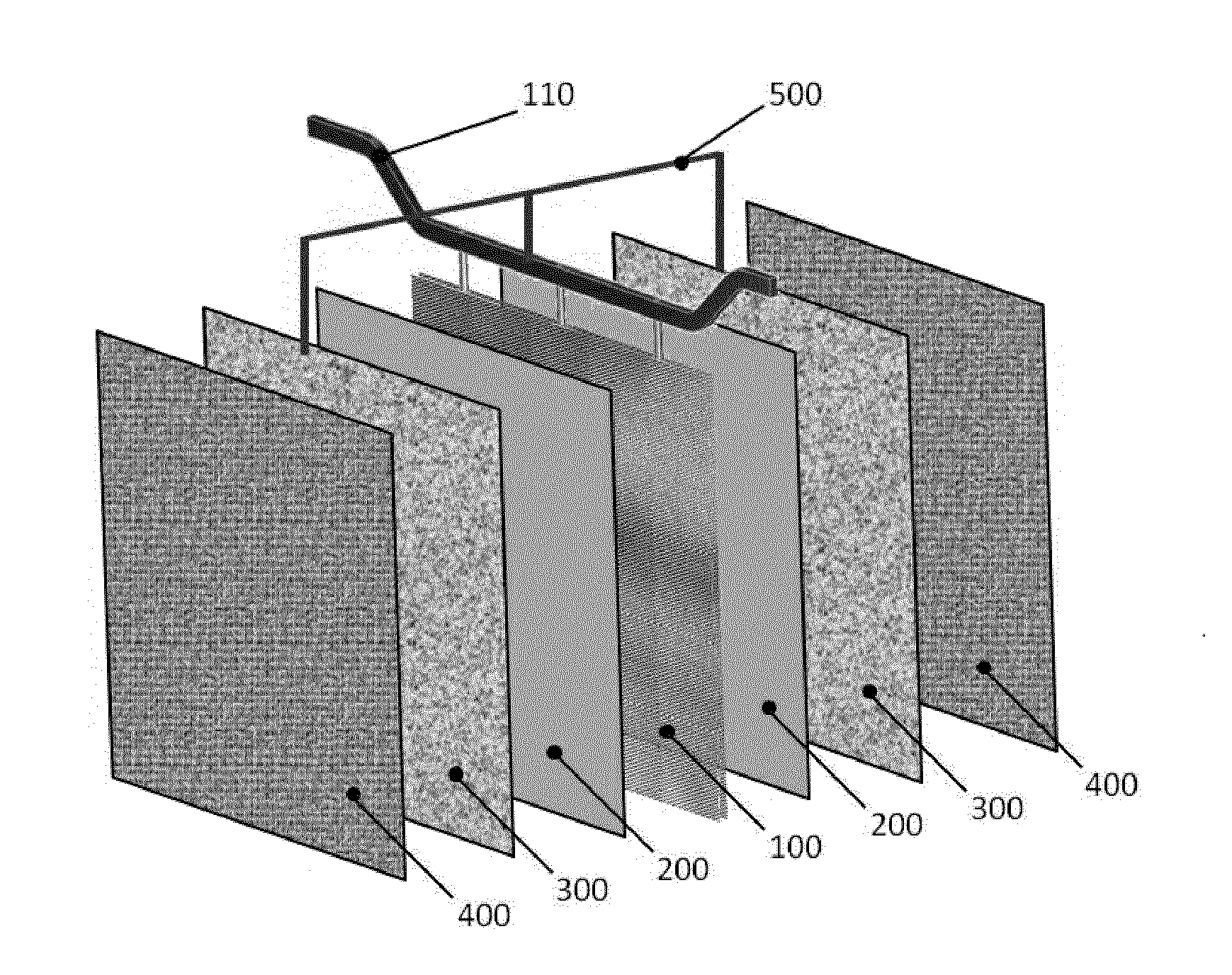
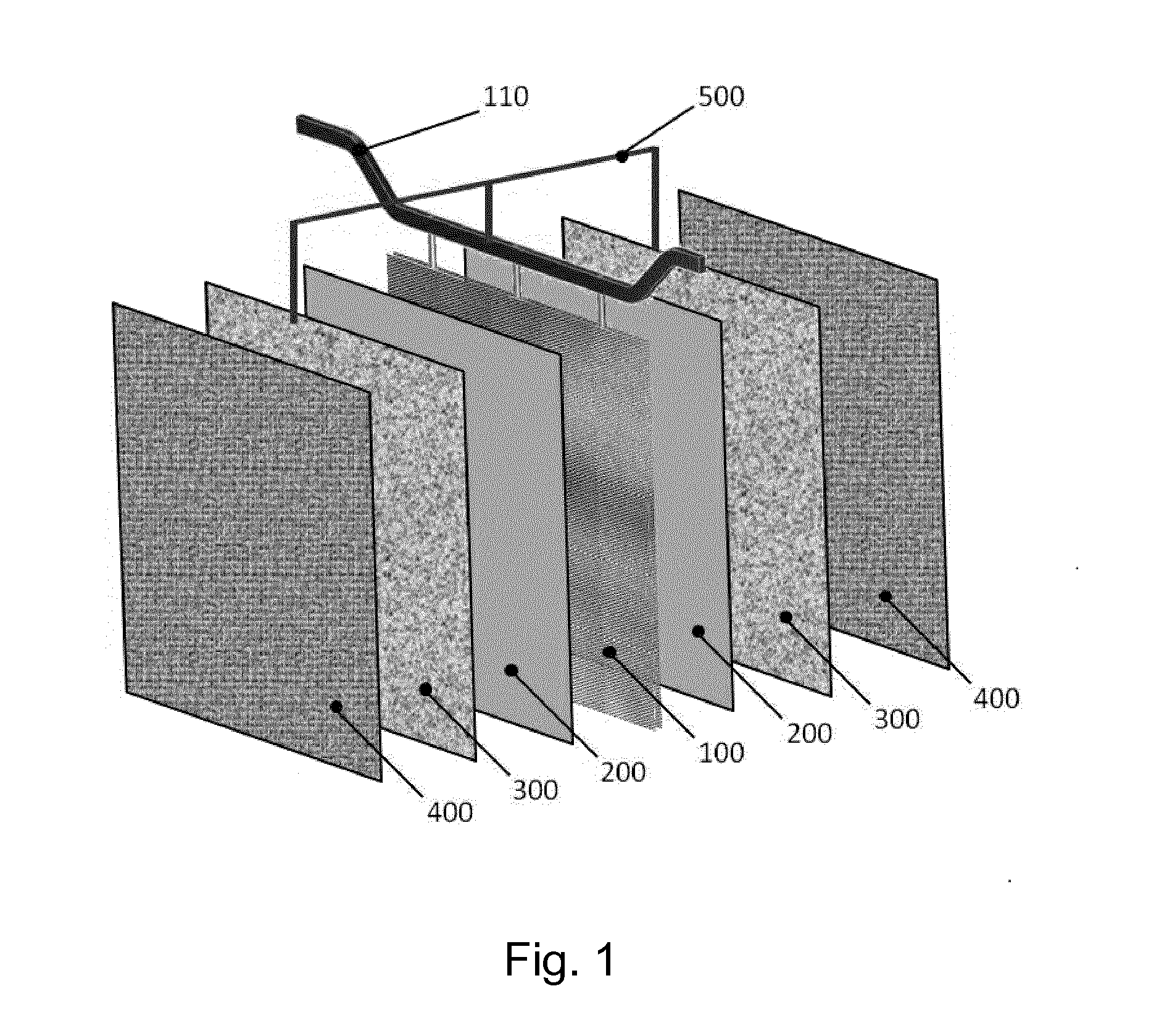
[0016]A laboratory test campaign was carried out inside a single electrowinning cell having an overall cross section of 170 mm×170 mm and a height of 1500 mm, containing a cathode and an anode. A 3 mm thick, 150 mm wide and 1000 mm high sheet of AISI 316 stainless steel was used as the cathode; the anode consisted of a titanium grade 1, 2 mm thick, 150 mm wide and 1000 mm high expanded sheet, activated with a coating of mixed oxides of iridium and tantalum. The cathode and anode were positioned vertically face-to-face spaced apart by a distance of 40 mm between the outer surfaces.

[0017]Inside the gap between the anode and cathode, a screen consisting of a titanium grade 1, 0.5 mm thick, 150 mm wide and 1000 mm high expanded sheet coated with a layer of 21 g / m2 of tin oxide, was positioned spaced apart by 10 mm from the surface of the anode and electrically connected to the anode through a resistor having 1 Ω of electrical resistance.

[0018]The cell was operated with an electrolyte co...


PUM

PropertyMeasurementUnit
current densityaaaaaaaaaa
electrical resistanceaaaaaaaaaa
mutual distanceaaaaaaaaaa

Abstract

The invention relates to a cell for metal electrowinning equipped with a device useful for preventing the adverse effects of dendrite growth on the cathodic deposit. The cell comprises a porous conductive screen, positioned between the anode and the cathode, capable of stopping the growth of dendrites and avoiding that they reach the anode surface.

Description

FIELD OF THE INVENTION[0001]The invention relates to a cell for metal electrowinning, particularly useful for the electrolytic production of copper and other non-ferrous metals from ionic solutions.BACKGROUND OF THE INVENTION[0002]Electrometallurgical processes are generally carried out in undivided electrochemical cell containing an electrolytic bath and a multiplicity of anodes and cathodes; in such processes, such as the electrodeposition of copper, the electrochemical reaction taking place at the cathode, which is usually made of stainless steel, leads to the deposition of copper metal on the cathode surface. Normally cathodes and anodes are vertically arranged, interleaved in a face-to-face position. The anodes are fixed to suitable anodic hanger bars, which in their turn are in electrical contact with positive bus-bars integral with the cell body; the cathodes are similarly supported by cathodic hanger bars which are in contact with the negative bus-bars. The cathodes extracte...

Claims


Application Information

Patent Timeline
Patent Type & Authority Applications(United States)
IPC IPC(8): C25C7/00C25C7/04C25C7/02C25C1/12
CPCC25C7/00C25C1/12C25C7/04C25C7/02C25C7/06
Inventor FIORUCCI, ALESSANDROCALDERARA, ALICEIACOPETTI, LUCIANO
Owner IND DE NORA SPA
Why Eureka
Try Eureka