CuO - TiO2 NANOCOMPOSITE PHOTOCATALYST FOR HYDROGEN PRODUCTION, PROCESS FOR THE PREPARATION THEREOF

a technology of tio2 nanocomposites and photocatalysts, which is applied in the direction of catalyst activation/preparation, physical/chemical process catalysts, metal/metal-oxide/metal-hydroxide catalysts, etc., can solve the problems of non-renewable resources in nature and potential to damage the environment, commercial utilization damage to the environment, and non-renewable catalyst excitation sources

Active Publication Date: 2016-02-18
COUNCIL OF SCI & IND RES
View PDF6 Cites 15 Cited by
  • Summary
  • Abstract
  • Description
  • Claims
  • Application Information

AI Technical Summary

Benefits of technology

[0018]In another embodiment of the present in...

Problems solved by technology

Both industrial processing of fossil resources and its commercial utilization damaged the environment.
Some of the above methods require higher temperature and pressure the resources are non-renewable in nature and potential to damage the environment.
Disadvantage of the prior art reported here, the excitation source of catalyst is non-renewable that is Ultra-Violet (UV) light emitted by Hg lamp,...

Method used


Image

  • CuO - TiO2 NANOCOMPOSITE PHOTOCATALYST FOR HYDROGEN PRODUCTION, PROCESS FOR THE PREPARATION THEREOF
  • CuO - TiO2 NANOCOMPOSITE PHOTOCATALYST FOR HYDROGEN PRODUCTION, PROCESS FOR THE PREPARATION THEREOF
  • CuO - TiO2 NANOCOMPOSITE PHOTOCATALYST FOR HYDROGEN PRODUCTION, PROCESS FOR THE PREPARATION THEREOF

Examples


examples

[0049]Following are the examples given to further illustrate the invention and should not be construed to limit the scope of the present invention.

example-1

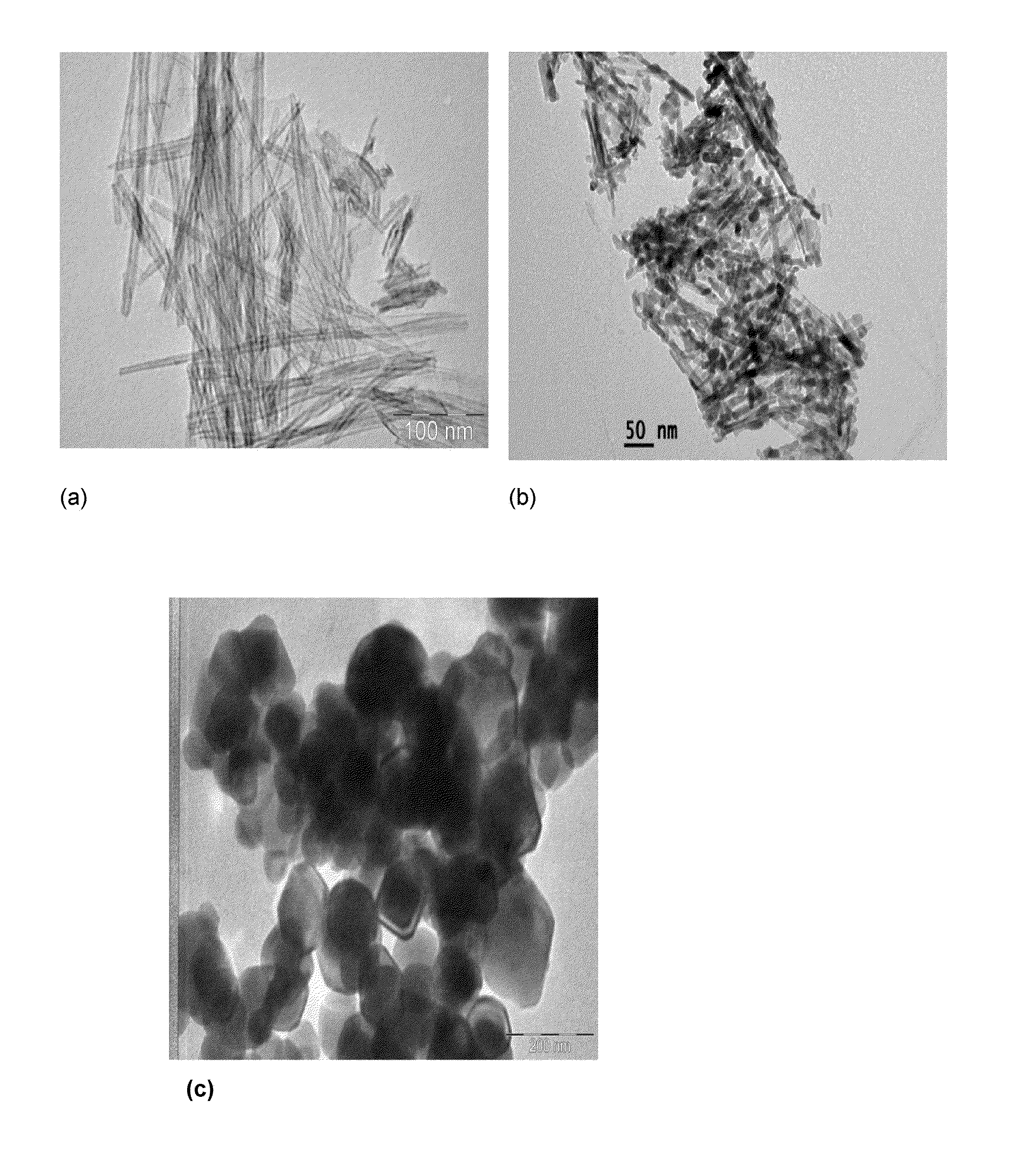
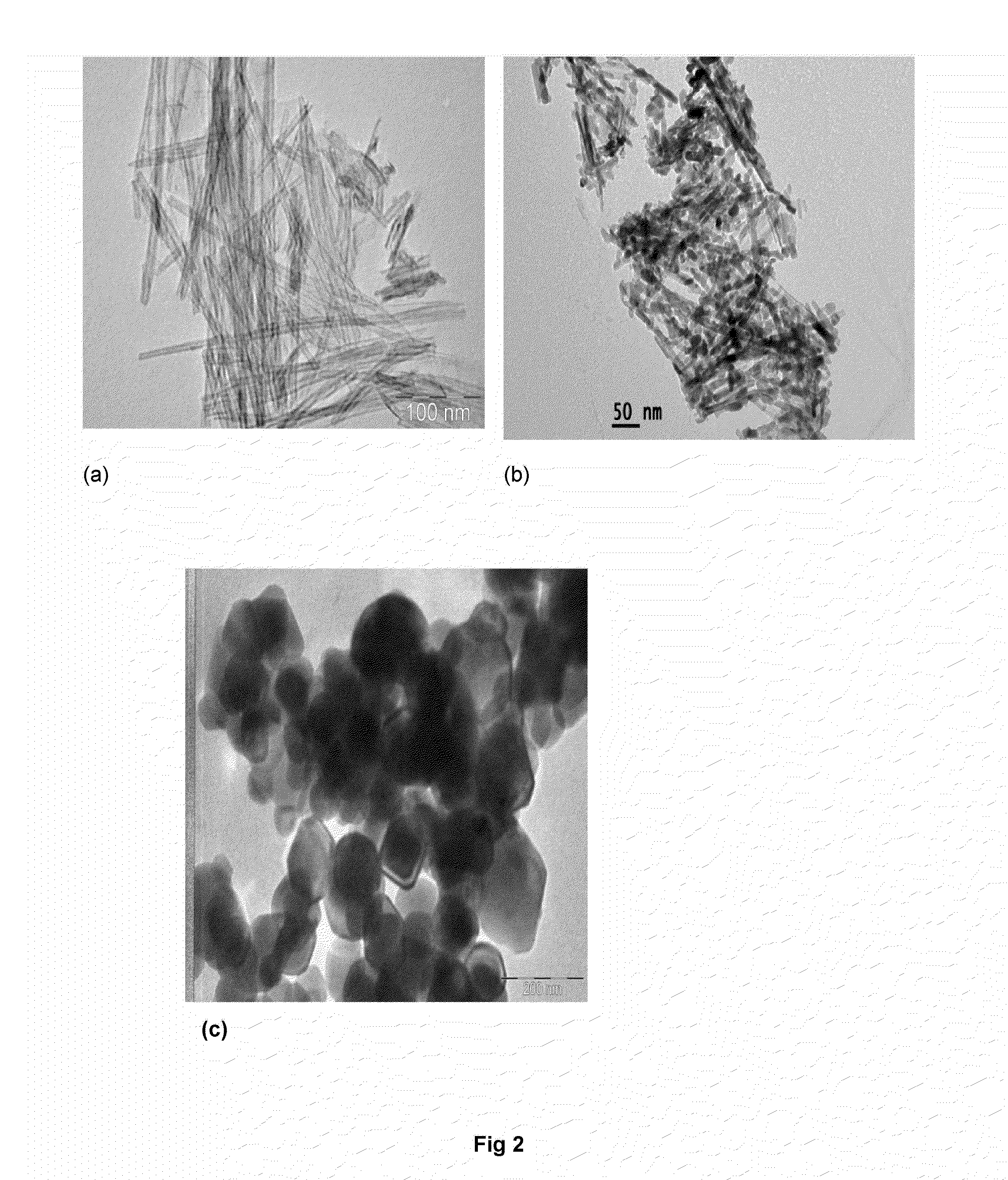
Synthesizing TiO2 Nano Tube (TNT)

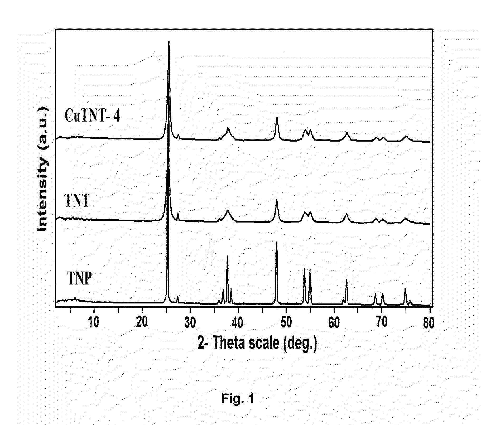
[0050]In a typical synthesis process, TiO2 (Merck) 0.1 μm average sized particles (TMP) (2.5 g,) was dispersed into 10 M NaOH (200 mL) aqueous solution under magnetic stirring for 1 h at 32±2° C. The homogeneous suspension was transferred into 250 mL teflon-lined autoclave and fitted with nuts and bolts. Then, the autoclave was kept in hot air oven at 130° C. for 20 h. The autoclave was removed from the oven and cooled-down to room temperature under tap water flow. At room temperature the autoclave was opened, discarded supernatant solution from white precipitate. Thus obtained white precipitate was subjected to washing in 3 steps under magnetic stirring for 2 hours and each step repeated twice: the precipitate was washed in distilled water, followed by 0.1 M HCl and absolute ethanol. Further, washed precipitate was subjected to drying in oven at 80° C. for 12 h and calcined at 350° C. for 5 h @ 2° C. / min.

[0051]The X-ray diffraction (XRD) patterns (F...

example-2

Preparation of CuO Dispersed TiO2 NT

[0052]Wet impregnation method of preparation was used for CuO dispersion on TiO2 NT (CuTNT-4). For each Cu modified sample, required amount of TiO2 nanotube (0.5 g) was dispersed into Cu(NO3)2.3H2O (0.028 g, 1.5 wt %, 10 mL water) concentration aqueous solution for 1 h at 110±2° C. Excess water was evaporated to dryness with slow heating and constant magnetic stirring. The sample was dried at 110° C. for at least 12 h and calcined at 350° C. for 5 h.

[0053]The X-ray diffraction (XRD) patterns (FIG. 1) of Cu-modified TiO2 nanotube catalysts were recorded with Siemens D-5000 X-ray diffract meter using Cu Kα radiation. A Philips Technai G2 FEI F12 transmission electron microscope operating at 80-100 kV was used to record the transmission electron microscopy (TEM) patterns (FIG. 2). The Diffuse Reflectance UV-Visible spectra (FIG. 3) were recorded on a GBC UV-visible Cintra 10e spectrometer, in the wavelength 200-800 nm range. X-ray photoelectron spect...


PUM

PropertyMeasurementUnit
Temperatureaaaaaaaaaa
Timeaaaaaaaaaa
Timeaaaaaaaaaa

Abstract

The present investigation is development of the TiO2 nanotubes concept of preparation of and their composite with fine dispersion of copper. The inventions also relates to identify a method for optimum amount of photocatalyst required for efficient and maximum hydrogen production reported than earlier (H2=99,823 μmol·h−1·g−1 catalyst) from glycerol-water mixtures under solar light irradiation. A method is disclosed to produce CuO/TiO2 nanotubes with high sustainability and recyclable activity for hydrogen production.

Description

FIELD OF THE INVENTION[0001]The present invention relates to CuO—TiO2 nanocomposite photocatalyst for hydrogen production, process for the preparation thereof. Particularly, the present invention provides a process for largest volume of hydrogen production in high yield than reported till date under solar light irradiation using CuO / TiO2 nanotubes photocatalyst. More particularly, the present invention relates to the hydrogen production under solar light irradiation using CuO / TiO2 nanotubes photocatalyst from Glycerol: water mixture.BACKGROUND OF THE INVENTION[0002]The demand for a large volume of fuel for transportation sector, for industrial use and increasing modern societal life-style is mainly supplied by petroleum based derivatives. Both industrial processing of fossil resources and its commercial utilization damaged the environment. Since the steady increase in fossil fuel requirements and decrease in natural fossil resources are at alarming rate that have urged to go for alt...

Claims


Application Information

Patent Timeline
IPC IPC(8): B01J35/06B01J19/12B01J21/06B01J23/72B01J35/00B01J37/03B01J37/08B01J37/34C01B3/04
CPCB01J35/06B01J2219/1203B01J23/72B01J21/063B01J35/004B01J37/08B01J37/031C01B3/042B01J19/123C01B2203/1217C01B2203/1076C01B2203/0277Y10S977/762Y10S977/811Y10S977/896B82Y40/00B82Y30/00B01J37/342B01J35/0013B01J35/002B01J35/006B01J37/0207Y02E60/36
Inventor KUMARI, VALLURI DURGASUBRAHMANYAM, MACHIRAJUSRINIVAS, BASAVARAJUSADANANDAM, GULLAPELLISHANKAR, MUTHUKONDA VENKATAKRISH NANSUNDAR, BETHANABHATLA SYAMAKUMARI, MURIKINATI MAMATHAKUMAR, DHARANI PRAVEEN
Owner COUNCIL OF SCI & IND RES
Why Eureka
Try Eureka