Methods of making and using microarrays suitable for high-throughput detection

a microarray and detection method technology, applied in the field of making and using microarrays suitable for highthroughput detection, can solve the problems of poor detection signal-to-background signal ratio, poor addressability, and reduce the sensitivity of the assay, and achieve the effect of minimalism of nois

Inactive Publication Date: 2016-03-03
UNIV OF UTAH RES FOUND
View PDF3 Cites 0 Cited by
  • Summary
  • Abstract
  • Description
  • Claims
  • Application Information

AI Technical Summary

Benefits of technology

[0011]It would be desirable to prepare microarrays that can optionally have uniformly shaped and sized sensing zones, and that are designed to allow high-throughput detection assays with minimal noise.

Problems solved by technology

However, a concern with using microarrays, particularly high-density microarrays, is that poor addressability can result due to the extremely small spaces between zones.
In high-density microarrays, these interstices can be very small (less than 100 microns), so even limited binding in these areas can produce poor detection signal-to-background signal ratios, reducing the sensitivity of the assay.
One of the limiting factors in the fabrication of high-density arrays is the uncertainty of the size distribution of sensing zones, which leads, in turn, to possible cross-talk between adjacent zones.
However, uncertainties with surface preparation (e.g., roughness, hydrophobicity, uniformity of functional modifications) and mass transport effects make this task challenging when the characteristic size of the feature is very small (less than 10 μm) or very big (˜100 μm).

Method used


Image

  • Methods of making and using microarrays suitable for high-throughput detection
  • Methods of making and using microarrays suitable for high-throughput detection
  • Methods of making and using microarrays suitable for high-throughput detection

Examples


example 1

Preparation of Microarray with Wells

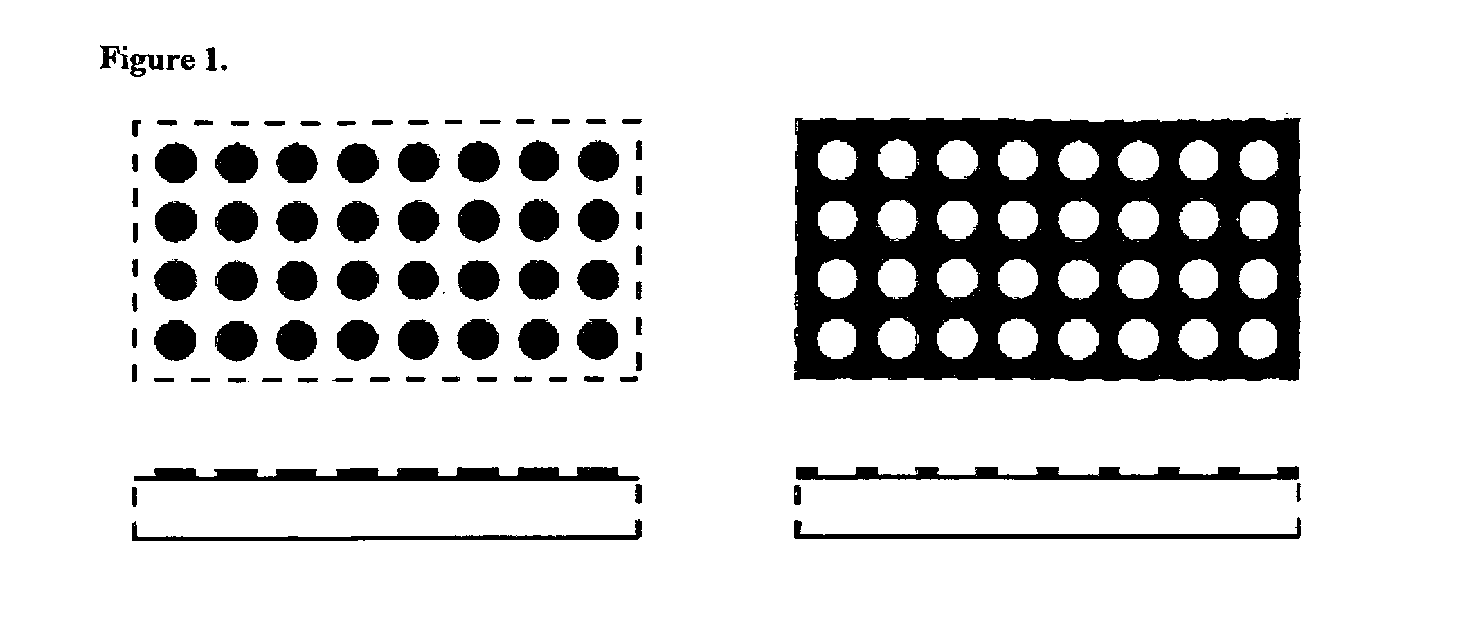
[0071]A 50 nm-thick gold cladding layer is applied to the upper surface of a standard glass microscope slide by chemical vapor deposition or sputtering. Positive photoresist is spin-coated onto the cladding layer and heated to drive off any remaining solvent. Upon cooling, the photoresist is exposed to UV radiation applied through a mask bearing an array of round holes, so that the radiation incident on the surface consists of an array of round spots having a diameter of 8 μm with center-to-center spacing of 10 μm. Exposure is maintained for a suitable amount of time to cause the photoresist to be sufficiently exposed to generate the material modification. The slide is then washed to remove any soluble resist. The result is an array of holes in the resist having the same dimensions and spacing as the UV light spots and within which the gold cladding layer is exposed. The exposed gold is etched away, followed by removal of the cured photoresist, to...

example 2

Preparation of Microarray with Islands

[0072]In another preferred embodiment, the substrate is glass and the cladding layer is a metal such as Au of 50 nm thickness. The Au layer is etched, leaving behind round “islands” of 8 micron diameters and 10 micron spacings. The regions between islands are glass. Attachment of the molecular probes to the islands can occur through thiol-active methods [include protein disulphide bonds].

example 3

Immobilization of Probe Molecules within the Sensing Zones

[0073]The slides are exposed to an RF induced oxygen at 400 mTorr in a March Plasmod for 5 minutes. This chemically modifies the exposed glass in the microarray wells and leaving the gold cladding inert. After the oxygen plasma the slides are immediately placed in a vapor deposition chamber containing 0.5 ml of 3-glycidoxypropyldmethylethoxysilane (GPS). The chamber is pumped down to 3 mTorr and heated to 115° C. which allows the GPS to vaporize and attached to the modified microarray well surfaces. After 16 hours in the vapor deposition chamber the slides are removed and to be spotted with oligonucleotide probes or stored for use at a later time. Immobilization is done with the oligonucleotide probes in a phosphate buffer at 150 mM with a pH of 8.5. An aliquot of probe is placed on the desired microarray well for 30 minutes at room temperature in a humid chamber followed by 30 minutes at 75° C. in a humid chamber. After the ...


PUM


Abstract

Disclosed are high density microarrays and methods for making and using such microarrays. The microarrays of the present invention can have uniformly shaped and sized sensing zones and are designed to allow high-throughput detection assays with minimal noise.

Description

CROSS-REFERENCE TO RELATED PATENT APPLICATIONS[0001]This application claims priority to U.S. Provisional Application No. 60 / 964,661 titled Method of Making Microarrays Suitable for High-Throughput Detection, filed on Aug. 13, 2007. In their entirety, the contents of this provisional application are herein incorporated into this non-provisional application.BACKGROUND OF THE INVENTION[0002]Microarrays are a powerful tool for obtaining quantitative and qualitative information about the composition of samples, particularly from biological sources such as tissues, cells, or viruses. Further, such systems also provide the ability to conduct a large number of parallel analyses on a single small platform. The basic concept behind microarray analysis is to create an addressable interrogation space in which specific addressable units (sensing zones) interact with specific components of a sample and produce a signal that provides information about the identity and quantity of those components....

Claims


Application Information

Patent Timeline
Patent Type & Authority Applications(United States)
IPC IPC(8): B01J19/00
CPCB01J19/0046B01J2219/00596B01J2219/00626B01J2219/00621B01J2219/00612B01J2219/00317B01J2219/00432B01J2219/00529B01J2219/00637B01J2219/00617B01J2219/00635B01J2219/00608
Inventor CHAGOVETZ, ALEXANDERBLAIR, STEVEN, M.WILSON, COLBY
Owner UNIV OF UTAH RES FOUND
Why Eureka
Try Eureka