Three-terminal stt-mram and method to make the same
- Summary
- Abstract
- Description
- Claims
- Application Information
AI Technical Summary
Benefits of technology
Problems solved by technology
Method used
Image
Examples
embodiment one
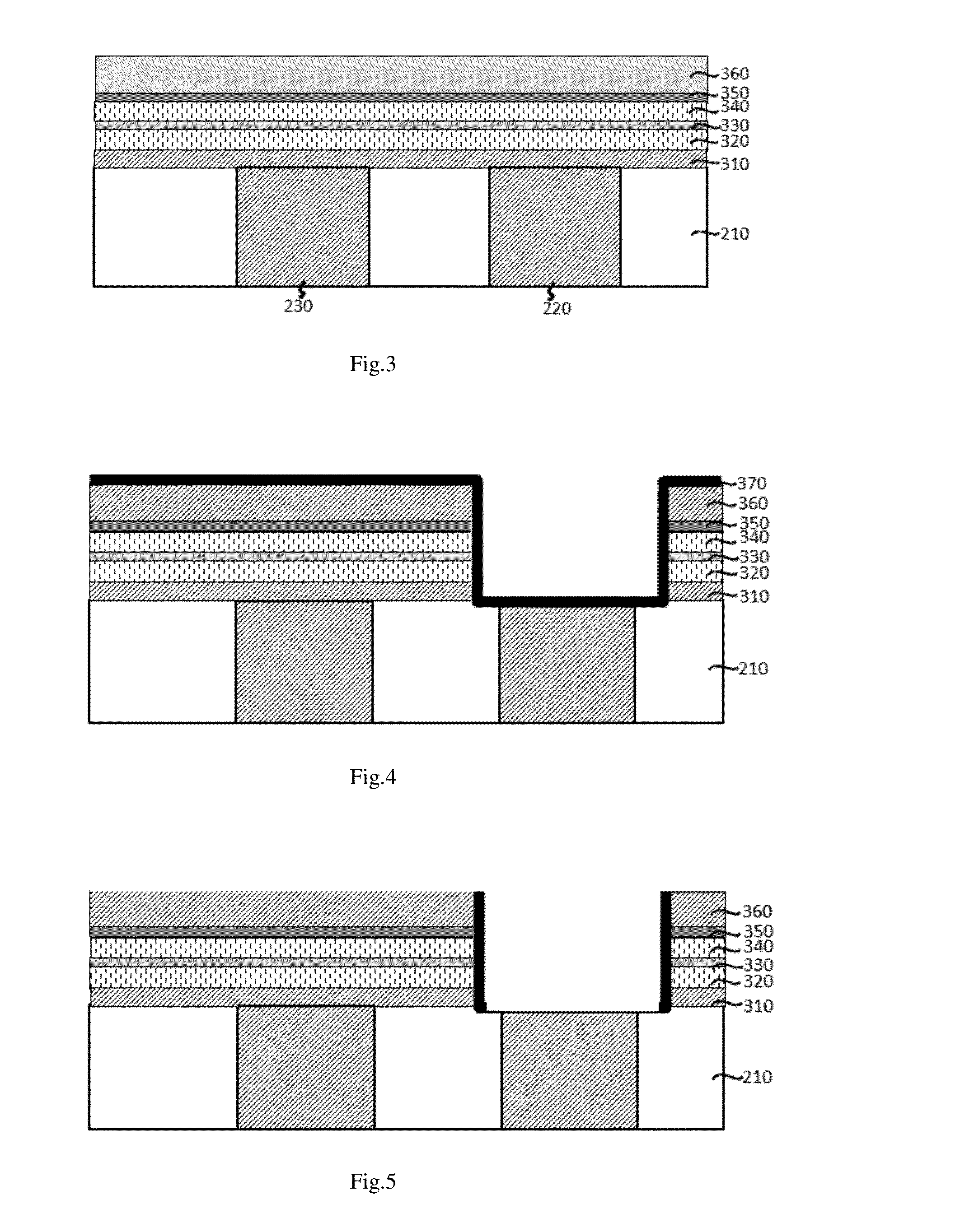
[0045]As shown in FIG. 4, a photolithography and etching is used to remove the memory multilayer to open a hole right on top of the VIA, and subsequently a dielectric insulating layer or so-called ILD (370) is conformally deposited over the exposed areas by a so-called atomic layer deposition (ALD) method.
[0046]Then a low angle milling or perpendicular sputter etching is used to remove the ILD film from the bottom and top flat area, leaving only the vertical wall still protected by the ILD (FIG. 5).
[0047]Then, by electric plating, the VIA hole is filled with a conducting material (380). Then, the top surface is flattened by a chemical mechanical polishing (CMP) process (FIG. 6).
[0048]Then, a second photolithography patterning and etching is used to form a hard mask pillar (360) cap, and the etching stops in the middle of top ILD layer (350) controlled by an end point detector (FIG. 7).
[0049]Then, another ILD is conformally deposition all over the exposed areas (FIG. 8), followed by ...
embodiment two
[0053]In the second embodiment, the process starts after deposition of the magnetic multi-layer (FIG. 3). With a photolithography patterning, the majority of the memory film stack is removed and only the areas for the memory cell remain (FIG. 13).
[0054]Then, the etched area is refilled by dielectrics (370, SiO2 or Si3N4) and surface is flattened by CMP (FIG. 14).
[0055]Then, a second photo patterning and etching / milling is used to form a memory pillar cap (360) and the etching stop in the middle of the top ILD layer (FIG. 15).
[0056]Then an ILD layer (380) is conformally deposited all around the etched surface by ALD method (FIG. 16).
[0057]Followed by a low angle mill / or perpendicular sputtering etch to remove the ILD from the top and bottom flat portion of the area, leaving on the vertical wall still covered by the ILD (FIG. 17A).
[0058]Then, a photolithography and etchin is used to remove dielectric layer and open a hole on top of the VIA (FIG. 17B).
[0059]Then, an electric plating is...
PUM
 Abstract
Description
Claims
Application Information
 - R&D
- Intellectual Property
- Life Sciences
- Materials
- Tech Scout
- Unparalleled Data Quality
- Higher Quality Content
- 60% Fewer Hallucinations
Browse by: Latest US Patents, China's latest patents, Technical Efficacy Thesaurus, Application Domain, Technology Topic, Popular Technical Reports.
© 2025 PatSnap. All rights reserved.Legal|Privacy policy|Modern Slavery Act Transparency Statement|Sitemap|About US| Contact US: help@patsnap.com


