Charged Particle Radiation Device and Specimen Preparation Method Using Said Device

a radiation device and charge particle technology, applied in the direction of manufacturing tools, lighting and heating apparatus, instruments, etc., can solve the problems of difficult to analyze the original structure of the sample, the temperature of the sample rises, etc., and achieve the effect of stably processing and observed, and high accuracy

Active Publication Date: 2016-03-10
HITACHI HIGH-TECH CORP
View PDF3 Cites 13 Cited by
  • Summary
  • Abstract
  • Description
  • Claims
  • Application Information

AI Technical Summary

Benefits of technology

[0018]According to the present invention, a sample in a frozen state retained on a first sample holder can be suspended as is in a bulk shape and then remounted on a second sample holder for thin film observation that is retained in a cooled state to prepare a thin film. Therefore, a thin film sample in which a desired portion of observation has been processed with high accuracy can be prepared without degrading the quality of the sample or contaminating the sample. Thereby, even a material that is sensitive to heat can be stably processed and observed while being maintained in its original shape. Problems, constitutions, and effects other than those explained above will be clarified by the explanations of the embodiments below.

Problems solved by technology

In processing or observation of a sample using a charged particle beam device, the temperature of the sample rises due to the energy of the charged particle beam, and there are cases in which it can be difficult to analyze the original structure of the sample.

Method used


Image

  • Charged Particle Radiation Device and Specimen Preparation Method Using Said Device
  • Charged Particle Radiation Device and Specimen Preparation Method Using Said Device
  • Charged Particle Radiation Device and Specimen Preparation Method Using Said Device

Examples


embodiment 1

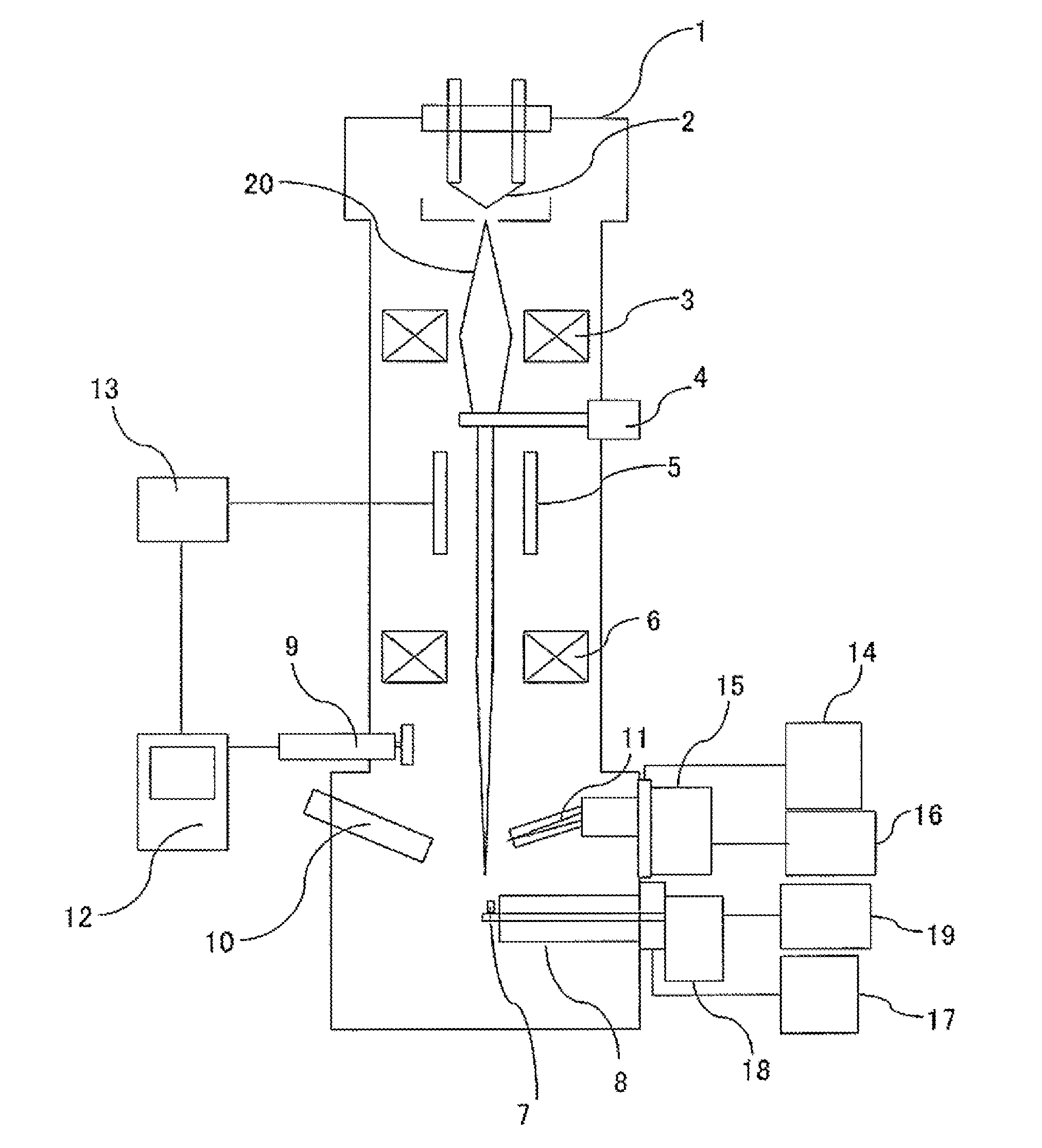
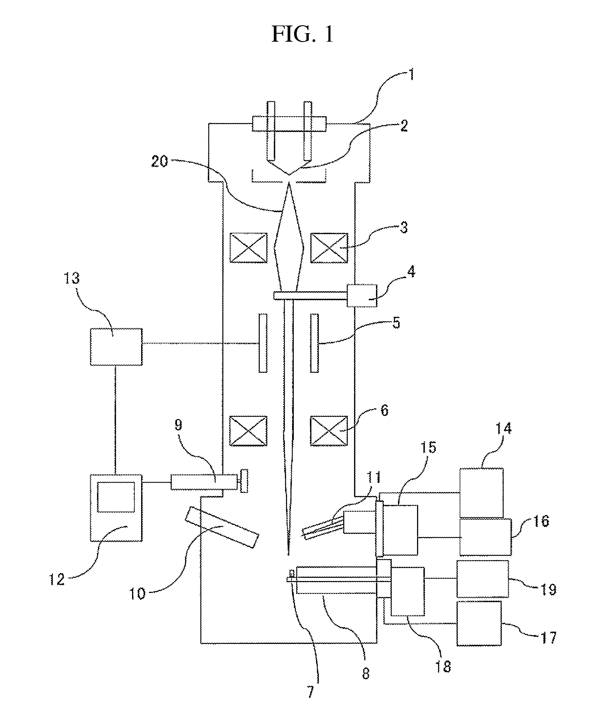
[0035]In the present embodiment, a FIB device that prepares a thin film sample from a cooled or frozen sample, a sample holder that retains a cooled state, and a method for preparing a thin film sample from a sample will be explained. FIG. 1 is a constitutional view of a FIB device 1. A mirror body of the FIB device 1 is constituted by an ion source 2, a condenser lens 3, a diaphragm 4, a scanning electrode 5, and an objective lens 6. In a sample chamber of the FIB device 1, a secondary electron detector 9 is attached above a sample holder 8 to which a sample 7 is attached, and a cold trap 10 for preventing contamination such as frost adherence on the sample 7 and a microprobe 11 for conveying a micro sample piece prepared by FIB processing are also attached. The microprobe 11 can be also introduced into another charged particle beam device other than a FIB device. A scanning image display device 12 is connected to the secondary electron detector 9. The scanning image display device...

embodiment 2

[0043]FIGS. 4(a) and 4(b) are constitutional views of the microprobe 11. One end of the microprobe 11 has the probe control device 14 (refer to FIG. 1) and the temperature adjustment device 16 (refer to FIG. 1). The microprobe 11 includes therein a microprobe thermal conduction rod 401 that is connected at one end to the microprobe cooling source container 15 (refer to FIG. 1), and is configured such that the cooling source temperature is transmitted up to the distal end of the microprobe. The microprobe cooling source container 15 and the microprobe distal end side are integrated, and thus can be easily attached / detached in a charged particle beam device and introduced into another charged particle beam device.

[0044]FIG. 4(a) illustrates a usage embodiment in a state in which the microprobe 11 is mounted on the FIB device 1. When removing the microprobe 11 to the outside of the FIB device 1 for transport, an external cover 402 is closed before transport in order to prevent water va...

embodiment 3

[0046]FIGS. 5(a) to 5(e) illustrate the steps of a transport process of the microprobe 11. FIG. 5(a) shows a state in which the sample 7 of an appropriate size has been cut away from a cooled base material sample in the FIB device 1, fixed to the microprobe 11, and extracted. The extracted sample 7 is in a cooled state by thermal conduction from the cooling source on the rear end of the microprobe 11. The extracted sample 7 can be retained at a vacuum degree equivalent to the vacuum degree inside the FIB device 1 due to the mechanism in which the sample 7 can be accommodated inside the microprobe outside cover 402 in the vacuum space of the FIB device 1 (FIG. 5(b)). In a state in which the microprobe 11 is accommodated inside the microprobe outside cover 402, the microprobe 11 is removed from the FIB device 1 to the outside of the device (FIG. 5(c)). At this time as well, the inside of the microprobe outside cover 402 is maintained at the vacuum degree of the FIB device 1, and the s...


PUM

PropertyMeasurementUnit
temperatureaaaaaaaaaa
thicknessaaaaaaaaaa
fixed temperatureaaaaaaaaaa

Abstract

The present invention enables a sample to be observed in a clean state directly after preparation of a final observation surface when preparing a sample for observing a material that is sensitive to heat. The present invention is a method of preparing a sample using a charged particle beam device including a microprobe having a cooling mechanism, a first sample holder having a mechanism for retaining a sample in a cooled state, and a stage into which the microprobe and the first sample holder can be introduced, the method including cutting a bulk-shaped sample piece from the sample on the first sample holder retained in a cooled state; adhering the sample piece to a distal end of the microprobe that is cooled to a fixed temperature and transferring the sample piece to a second sample holder for thin film observation retained in a cooled state, which is different from the first sample holder, within a vacuum chamber of the charged particle beam device; separating the sample piece that has been transferred to the second sample holder from the microprobe and thin film processing the sample piece to a thickness that is less than the thickness during cutting; and observing the sample piece after the thin film processing.

Description

TECHNICAL FIELD[0001]The present invention relates to a charged particle beam device having a charged particle source (for example, an ion source or an electron beam source) as well as a sample preparation method using the device.BACKGROUND ART[0002]Recently, Scanning Electron Microscopy (hereinafter referred to as “SEM”), Transmission Electron Microscopy (hereinafter referred to as “TEM”), or Scanning Transmission Electron Microscopy (hereinafter referred to as “STEM”) are often used to analyze a sample having a fine structure. Before introducing a sample into these observation devices, it is necessary to prepare a cross section or thin film of the sample, and thus a Focused Ion Beam (hereinafter referred to as “FIB”) device is used. A method for FIB processing an observation portion into a thin film shape is called FIB microsampling, and this is the most suitable sample preparation method when using electron microscopy and the like to analyze the condition / structure on the order o...

Claims


Application Information

Patent Timeline
Patent Type & Authority Applications(United States)
IPC IPC(8): H01J37/20B25J7/00G01N1/42H01J37/28H01J37/30
CPCH01J37/20H01J37/28H01J37/30B25J7/00H01J2237/2001H01J2237/202H01J2237/2007H01J2237/31749H01J2237/2801G01N1/42G01N2001/2873H01J37/302H01J37/304H01J37/3056H01J2237/002H01J2237/208H01J2237/30461H01J2237/31745
Inventor TSUCHIYA, MIKINAGAKUBO, YASUHIRATOMIMATSU, SATOSHI
Owner HITACHI HIGH-TECH CORP
Why Eureka
Try Eureka