Multi-junction artificial photosynthetic cell with enhanced photovoltages

a photovoltaic cell and multi-junction technology, applied in the field of photoelectrocatalytic devices and methods, can solve the problems of limiting the exploitation of a substantial portion of the solar spectrum, high cost and complexity of device fabrication using triple junction a-, and the insufficient stable operation in harsh electrochemical conditions for long hours, etc., to achieve the reduction of co2 to fuels and chemicals, the effect of reducing the amount of free energy for water and reducing the amount of co

Active Publication Date: 2016-03-17
HYPERSOLAR +1
View PDF1 Cites 3 Cited by
  • Summary
  • Abstract
  • Description
  • Claims
  • Application Information

AI Technical Summary

Benefits of technology

[0008]Disclosed herein are multi-junction photosynthetic units with novel architecture from simple low-cost electrochemical approaches. The embodiments disclosed herein provide sufficient free energy to split water and / or reduce CO2 to fuels and chemicals in an efficient and stable manner.
[0009]Certain embodiments include the use of low-cost synthetic techniques to obtain semiconductor materials with designed composition, size and shape control. Certain embodiments include semiconductor materials containing earth abundant elements. Certain embodiments include a nano porous aluminum oxide template to create fault-tolerant systems that defy photo-corrosion and other degradative effects of a harsh electrochemically active environment.

Problems solved by technology

However, water oxidation at photo-anode is a kinetically sluggish process and likewise CO2 reduction at photo-cathode needs high overpotentials, resulting in actual energy requirements greater than 2.0 V. Therefore, using a single light absorber unit for water splitting or CO2 reduction requires a semiconductor with large band gap (Eg>2.5 eV), limiting the exploitation of a substantial portion of the solar spectrum.
However, the high costs and complexities associated with device fabrication using triple junction a-Si, (Weber, M.
Moreover, their stable operation in harsh electrochemical conditions for long hours remains insufficient.

Method used


Image

  • Multi-junction artificial photosynthetic cell with enhanced photovoltages
  • Multi-junction artificial photosynthetic cell with enhanced photovoltages
  • Multi-junction artificial photosynthetic cell with enhanced photovoltages

Examples


Embodiment Construction

I. Artificial Photosynthetic Unit Overview

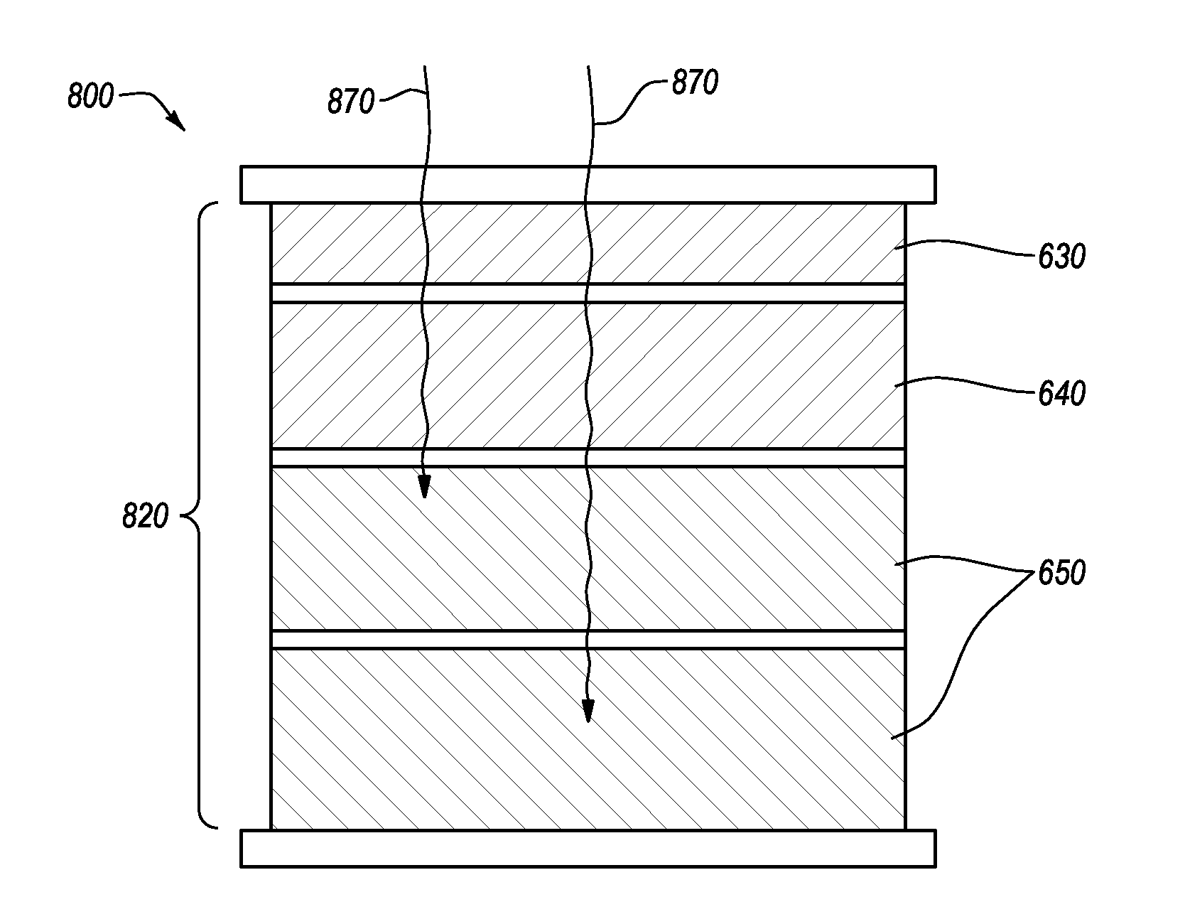
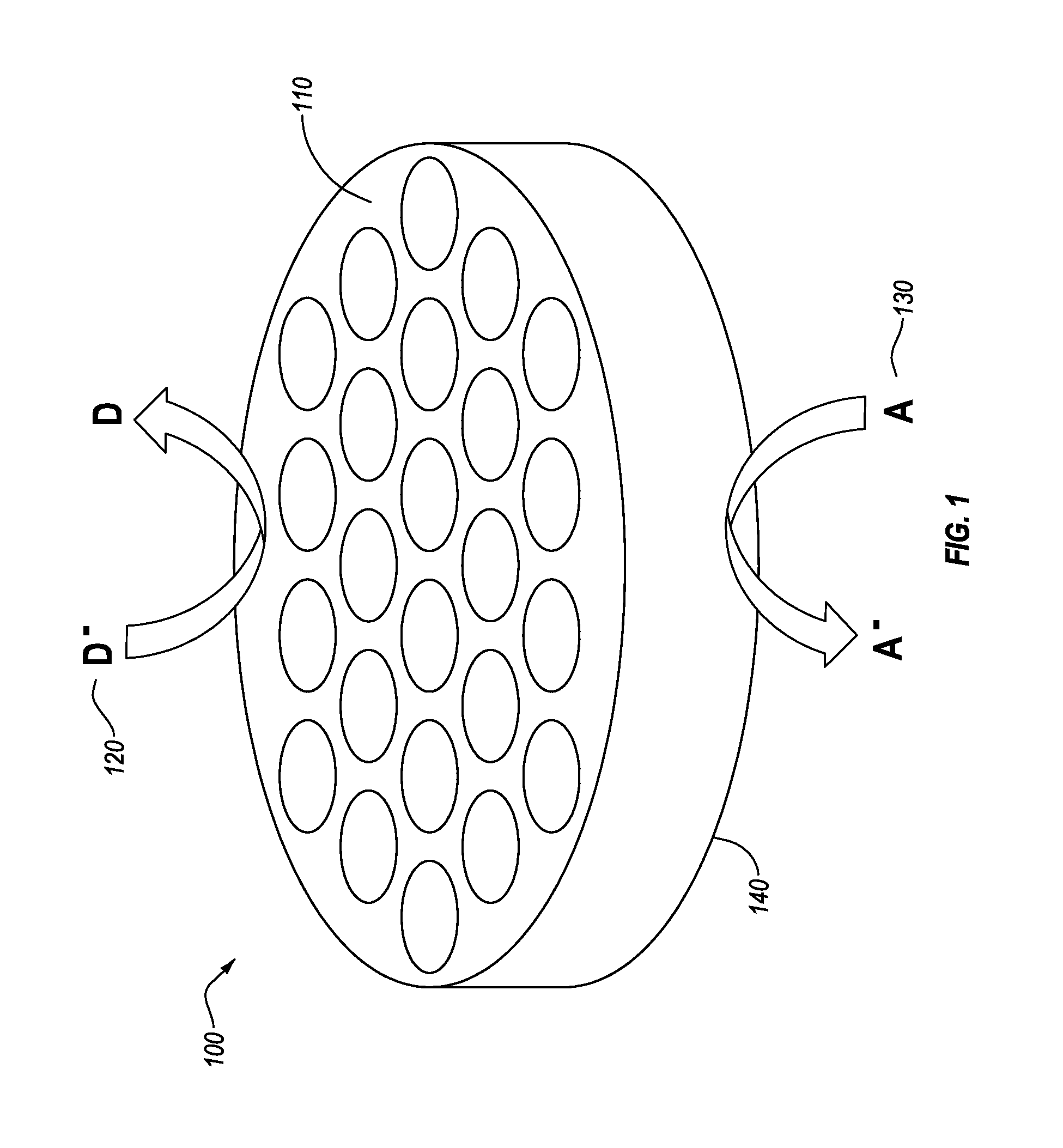
[0027]An exemplary multi-junction photosynthetic unit 100 is shown in FIG. 1. The illustrated embodiment is a self-contained photocatalytic nanoreactor unit by which solar photons are transformed into electronic excitations which can be separated into electrons and holes which will move to the catalyst / electrolyte interface 110 of the structure and transfer to acceptor / donor surface species 120, 130. To prevent the oxidation from scavenging the electrons (via back reaction), a coating permeable to H+ and H2 (for water splitting) and CO2 (for CO2 reduction) can be applied to the outer surface of the cathodic end 140 of the structure. Effectively, this moves the expensive ion-selective membrane used in most water splitting systems and electrolyzers to the surface of the catalyst.

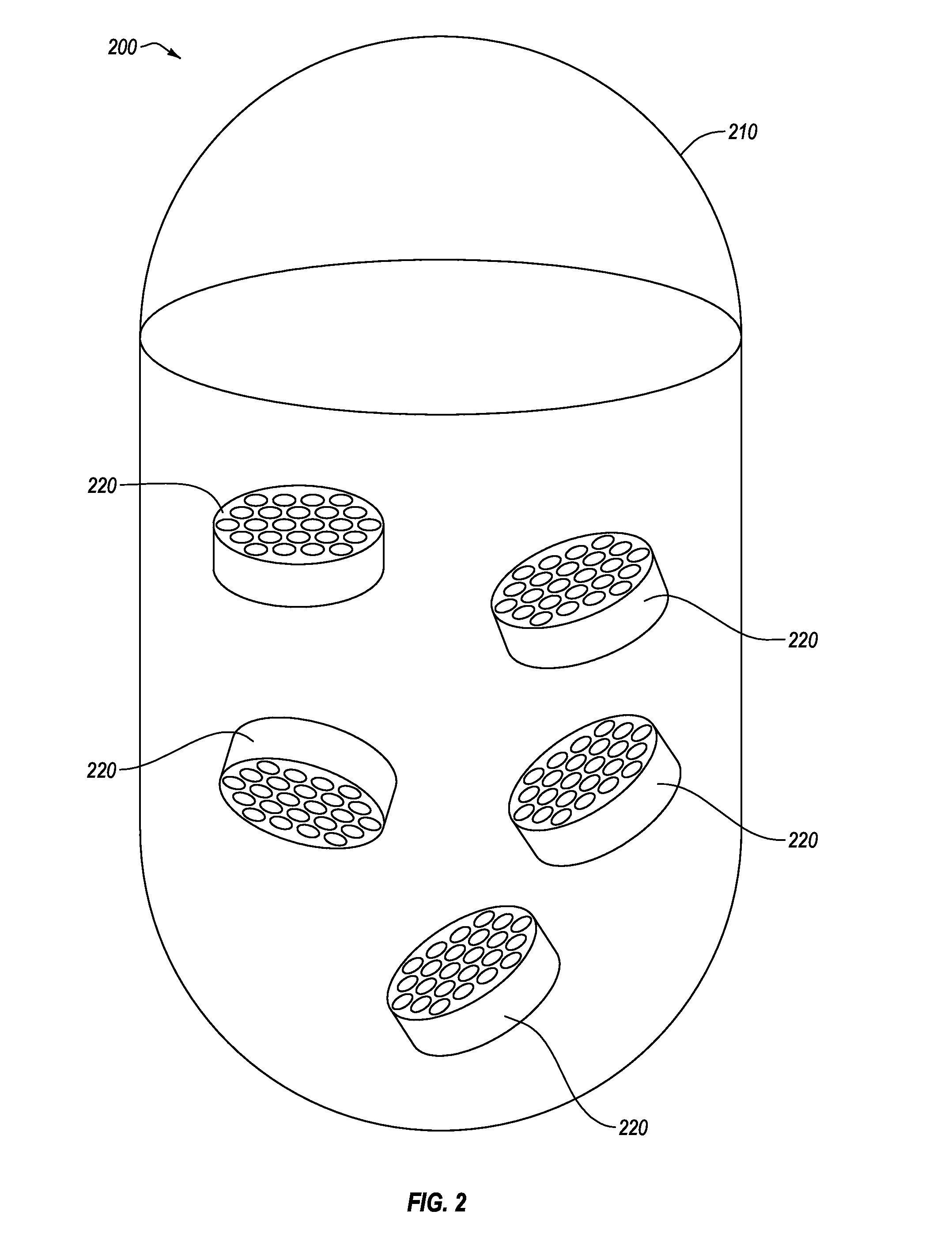
[0028]FIG. 2 illustrates an embodiment of a photoreactor system 200 formed as a reactor vessel 210 including a plurality of multi-junction photosynthetic units 220 sus...


PUM

PropertyMeasurementUnit
photovoltageaaaaaaaaaa
photovoltagesaaaaaaaaaa

Abstract

A multi-junction artificial photosynthetic unit includes an active element with a plurality of semiconducting layers, with metal layers deposited between the semiconductor layers appropriately forming Schottky barrier junctions or ohmic junctions with a surface of an adjacent semiconductor layer. The active element is formed within a protective structure formed of porous aluminum oxide. Successive layers of the active element can be formed within the protective structure, and additional layers and junctions can be added until desired photovoltages are achieved. A photoreactor for the production of fuels and chemicals driven by solar-powered redox reactions includes a bag reactor filled with a feedstock solution. A plurality of multi-junction photosynthetic units are placed in the feedstock solution to drive the redox reactions and produce the desired fuels and chemicals.

Description

CROSS-REFERENCE TO RELATED APPLICATIONS[0001]This application claims the benefit of U.S. Provisional Application No. 61 / 968,598 filed Mar. 21, 2014, the disclosure of which is incorporated herein in its entirety.BACKGROUND[0002]1. Field of the Invention[0003]Disclosed herein are photoelectrocatalytic devices and methods, including multi-junction artificial photosynthetic components and methods of use and manufacture thereof.[0004]2. Description of the Related Art[0005]Development of an inexpensive solar fuel conversion process for the cleavage of water and CO2 reduction could potentially generate fuels or industrial chemicals with net zero carbon emissions. Based on the thermodynamic requirements alone, solar radiation with photon energies greater than 1.23 electron-volts is required to split water or to reduce CO2 to fuels. However, water oxidation at photo-anode is a kinetically sluggish process and likewise CO2 reduction at photo-cathode needs high overpotentials, resulting in ac...

Claims


Application Information

Patent Timeline
Patent Type & Authority Applications(United States)
IPC IPC(8): C25B3/25H01G9/20H01L31/0224H01L31/048H01L31/07H01L31/0725H01L31/073H01L31/0749
CPCC25B1/003H01L31/0725H01L31/07H01L31/0481H01G9/20H01L31/0749H01L31/022425C25B1/04C25B9/00H01L31/073H01L31/032H01L31/078H01L31/043Y02E10/541Y02E10/543Y02E60/36Y02P20/133C25B1/55C25B3/25Y02E10/50
Inventor HUSSAINI, SYED MUBEEN JAWAHARMCFARLAND, ERIC W.MOSKOVITS, MARTINLEE, JOUNYOUNG, TIM
Owner HYPERSOLAR
Why Eureka
Try Eureka