Multilayer structure, method for producing same, and article

a multi-layer structure and production method technology, applied in the direction of manufacturing tools, electric/magnetic/electromagnetic heating, instruments, etc., can solve the problems of difficult to impart all of the optical performance, the surface of the fine relief structure exhibits lower abrasion resistance and durability, and the nanoscale convex portion is easily destroyed, etc., to achieve excellent optical performance and abrasion resistance, and high pencil hardness

Inactive Publication Date: 2016-03-24
MITSUBISHI CHEM CORP
View PDF5 Cites 24 Cited by
  • Summary
  • Abstract
  • Description
  • Claims
  • Application Information

AI Technical Summary

Benefits of technology

[0053]The multilayer structure of the invention exhibits excellent optical performance and abrasion resistance and has a high pencil hardness.
[0054]According to the method for producing a multilayer structure of the invention, it is possible to produce a multilayer structure which exhibits excellent optical performance and abrasion resistance and has a high pencil hardness.
[0055]The article of the invention exhibits excellent optical performance and abrasion resistance and has a high pencil hardness.
[0056]In addition, according to the invention, it is possible to provide a multilayer structure (laminate body) excellent in performance to prevent the reflection of light, performance to transmit light, mechanical properties and the like. The mechanical properties include the “resistance to steel wool abrasion” reflecting the scratch resistance and the like and the “pencil hardness” different from the resistance to steel wool abrasion, and these two properties are in a trade-off relationship, but according to the invention, these two properties are both favorable and can be sufficiently subjected to practical use. Hence, specifically, it is possible to provide a multilayer structure exhibiting excellent mechanical properties for an application such as the antireflection with respect to FPD or the like, an improvement in light transmissiveness, and the surface protection.

Problems solved by technology

However, the nanoscale convex portion on the surface of the fine relief structure is easily destroyed and the surface of the fine relief structure exhibits lower abrasion resistance and durability as compared with a smooth surface formed of the same resin.
However, it is difficult to impart all of the optical performance, the adhesion property to a substrate, the mechanical properties (abrasion resistance, pencil hardness, or the like) and the like to the layer consisting of the cured product of an active energy ray curable resin composition (fine relief structure layer) at a practical level.
In particular, abrasion resistance and pencil hardness which are regarded to be important as the mechanical properties have different mechanisms in the occurrence of scratches as to be described below, and thus it is difficult to enhance both the abrasion resistance and the pencil hardness.

Method used


Image

  • Multilayer structure, method for producing same, and article
  • Multilayer structure, method for producing same, and article
  • Multilayer structure, method for producing same, and article

Examples


examples

[0395]Hereinafter, the invention will be described in more detail with reference to Examples.

[0396][Test 1]

[0397]Various kinds of measurements and evaluation methods in Test 1, a method for fabricating a mold, and components used in the respective Examples are as follows.

[0398]“Measurement and Evaluation”

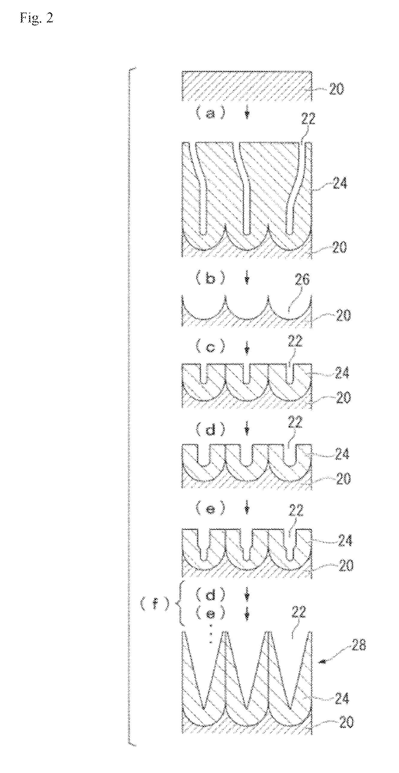
[0399](1-1) Measurement of Pore of Mold

[0400]A part of a mold was cut, the surface and longitudinal section of the cut mold was deposited with platinum for 1 minute and observed by enlarging 20,000 times at an accelerating voltage of 3.00 kV using a field emission scanning electron microscope (“JSM-7400F” manufactured by JEOL Ltd.), the interval between adjacent pores (distance from the center of a pore to the center of an adjacent pore) was measured at 50 points, and the average value thereof was adopted as the average interval (cycle) between adjacent pores.

[0401]In addition, the longitudinal section of the mold was observed by enlarging 30000 times, and the distance between the b...

example 1-1

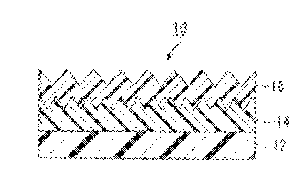
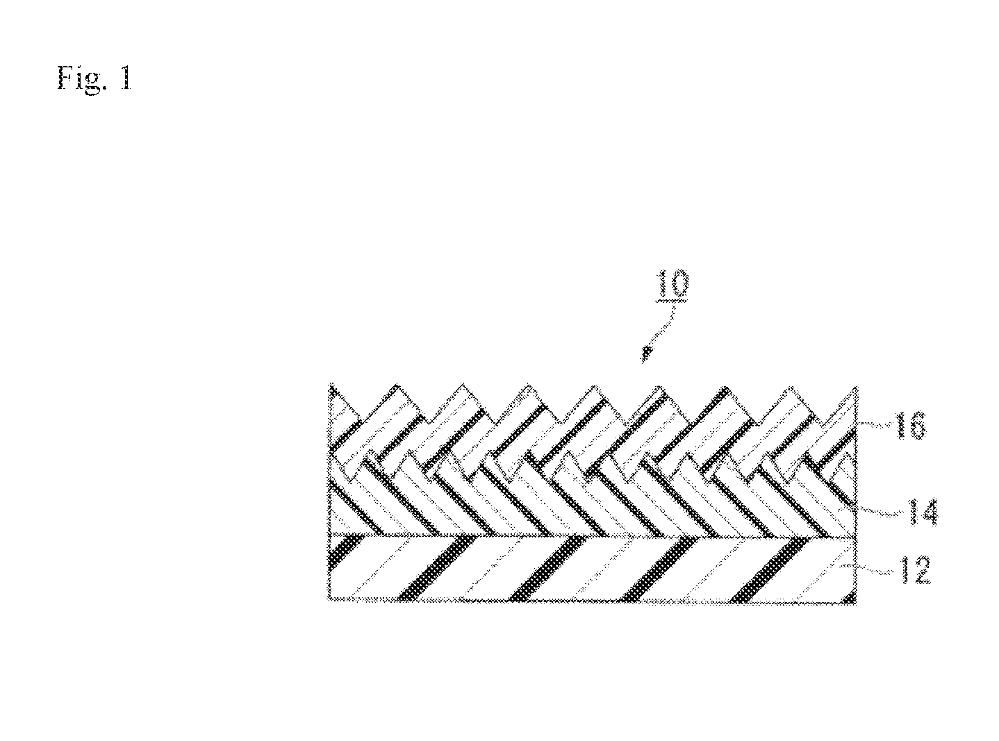
[0472](Step 1: Formation of Intermediate Layer)

[0473]Few drops of the resin composition A was dropped on the surface of the mold A. The resin composition A was covered with a triacetyl cellulose film (“TD8OULM” manufactured by FUJIFILM Corporation, hereinafter also referred to as the “TAC film”) having a thickness of 80 μm as the substrate while pressing and spreading the resin composition A with the TAC film. Thereafter, the resin composition A was cured by being irradiated with ultraviolet light at energy of 1000 mJ / cm2 from the TAC film side using a UV irradiating device (manufactured by Heraeus Noblelight BmbH). The cured product of the resin composition A was released from the mold A together with the TAC film, whereby a laminate film in which an intermediate layer having a fine relief structure having an average interval (cycle) between adjacent convex portions of 100 nm and an average height of the convex portions of 180 nm (aspect ratio: 1.8) on the surface and a film thickn...

examples 1-2

[0479]The multilayer structure was produced in the same manner as in Example 1-1 except that the resin composition D was changed to the resin composition E in the step 2, and the multilayer structure thus obtained was subjected to various kinds of measurements and evaluations. The results are presented in Tables 1 and 2.

[0480]Incidentally, the average intervals of adjacent convex portions, average heights of the convex portions, and aspect ratios of the fine relief structures formed on the surfaces of the intermediate layer and the outermost layer were the same as those in Example 1-1.


PUM

PropertyMeasurementUnit
wavelengthaaaaaaaaaa

Abstract

A base, an intermediate layer and an outermost layer are sequentially laminated. The intermediate layer has a Martens hardness of 120 N / mm2 or more; outermost layer has an- elastic modulus recovery ratio of 70% or more; and surface of outermost layer is provided with microrelief structure that has pitch not more than the wavelength of visible light. A method for producing the multilayer structure, comprises an active energy ray curable resin composition having a polymerizable functional group arranged on a light-transmitting base, and active energy ray irradiation carried out, forming an intermediate layer with rate of reaction of the polymerizable functional group in the surface is 35-85% by moleStep; an active energy ray curable resin composition (Y) arranged between the intermediate layer and a mold for microrelief structure transfer Step; and second active energy ray irradiation is carried out from the base side, to form an outermost layer.

Description

TECHNICAL FIELD[0001]The present invention relates to a multilayer structure, a method for producing the same, and an article.[0002]This application is based upon and claims the benefit of priority of the prior Japanese Patent Application No. 2013-079568 filed in the Japanese Patent Office on Apr. 5, 2013 and the prior Japanese Patent Application No. 2013-167825 filed in the Japanese Patent Office on Aug. 12, 2013, the entire contents of which are incorporated herein by reference.BACKGROUND ART[0003]Articles having a fine relief structure with a cycle equal to or less than the wavelength of visible light on the surface are known to have an antireflective performance due to a continuous change in refractive index of the fine relief structure. In addition, the fine relief structure is also known to exert super water repellent performance by the Lotus effect. However, the nanoscale convex portion on the surface of the fine relief structure is easily destroyed and the surface of the fin...

Claims


Application Information

Patent Timeline
Patent Type & Authority Applications(United States)
IPC IPC(8): B32B3/30B29C35/08B32B27/08B32B27/16
CPCB32B3/30B32B27/08B32B27/16B29K2033/04B32B2307/51B29C2035/0827B29C35/0805B29C35/10B29C39/148B29C41/26B29C59/046B32B27/06B32B2307/7265G02B1/118G02B5/0294
Inventor NAKAI, YUSUKEOTANI, GOOZAWA, SATORUJIGAMI, TETSUYA
Owner MITSUBISHI CHEM CORP
Why Eureka
Try Eureka