Reactor with Honeycomb Catalyst for Fuel Reformation

a catalyst and fuel technology, applied in the field of catalysts for fuel reformation, can solve the problems of increasing energy cost and energy shortage, dwindling fossil fuel availability, and complex traditional hydrogen production by steam reformation, and achieves high catalyst activity, high mass transfer efficiency, and reduced bed pressure

Active Publication Date: 2016-08-11
INST NUCLEAR ENERGY RES ROCAEC
View PDF0 Cites 5 Cited by
  • Summary
  • Abstract
  • Description
  • Claims
  • Application Information

AI Technical Summary

Benefits of technology

[0007]The main purpose of the present invention is to provide a fuel reformation reactor having a reduced bed pressure, a high catalyst activity and a high mass transfer efficiency for reaction having high space velocity of gas, where the problems of big bed pressure drop and bad thermal conductivity are solved; the problem that catalyst particles may be easily broken owing to the impact of thermal stress is solved; the reactor has a simple structure, a small size, a flexible operation and a low equipment and operation cost; a plurality of the reactors can be paralleled for expansion; and the present invention is suitable for generating hydrogen through methane reformation.

Problems solved by technology

However, available fossil fuel is dwindling.
In the foreseeable future, human will face increasing energy cost and energy shortage as well as other problems.
However, the traditional hydrogen production by steam reformation is complex and takes space.
When reactions are processed at high temperature by a reformer with nickel-based catalyst granules filled, there are problems occurred, like big pressure drop, poor thermal conductivity, catalyst granules easily broken owing to thermal stress impact, etc.
Yet, carbon deposition would appear; the catalyst might be powdered after the steam reformation; the hydrogen-rich gas produced at back end could cause pulse voltage drop with current instability; and, even more, catalyst dust and carbon deposits would pollute SOFC through gas pipelines and cause system crash.
Hence, the prior arts do not fulfill all users' requests on actual use.

Method used


Image

  • Reactor with Honeycomb Catalyst for Fuel Reformation
  • Reactor with Honeycomb Catalyst for Fuel Reformation
  • Reactor with Honeycomb Catalyst for Fuel Reformation

Examples


Embodiment Construction

[0012]The following description of the preferred embodiment is provided to understand the features and the structures of the present invention.

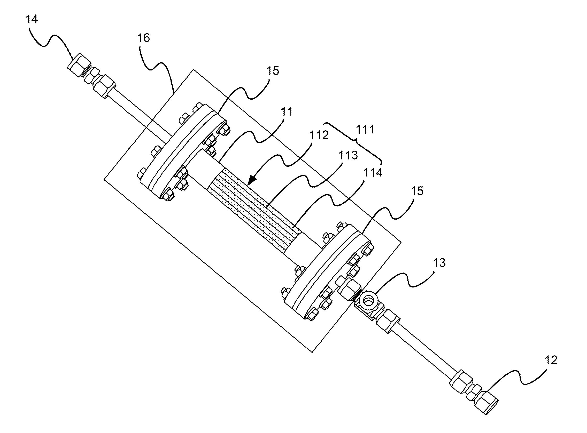
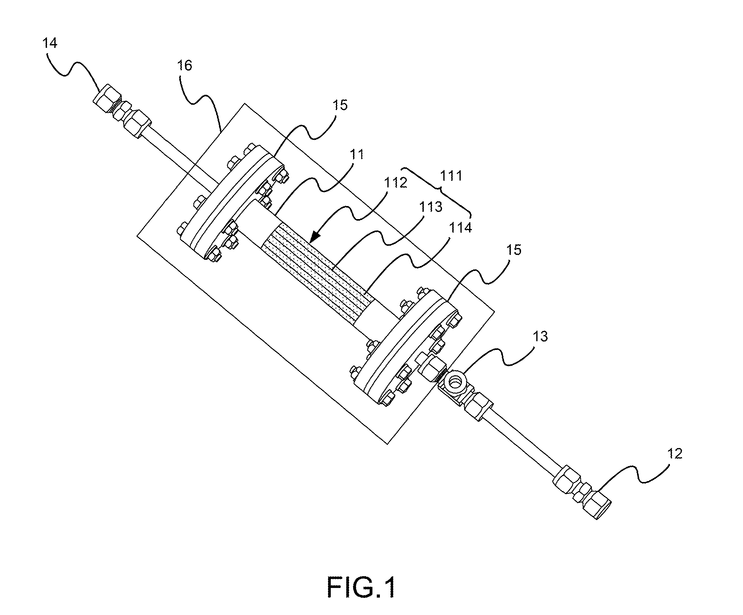
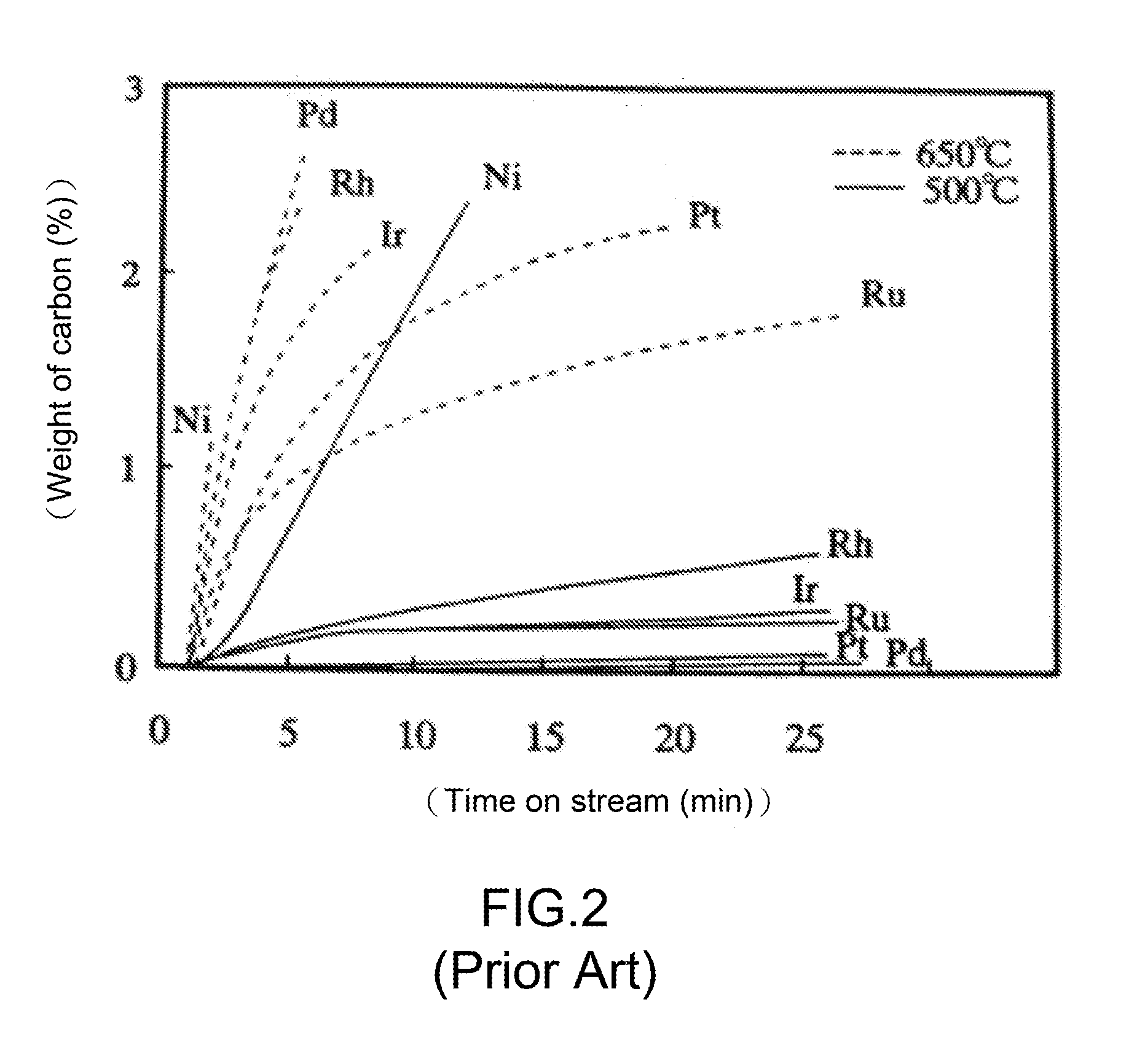
[0013]Please refer to FIG. 1 and FIG. 2, which are a structural view showing a preferred embodiment according to the present invention; and a view showing carbon deposition rates of different metal catalysts. As shown in the figures, the present invention is a reactor with honeycomb catalyst for fuel reformation, comprising a heating tube 11, a methane gas inlet 12, a three-way steam inlet 13 and a hydrogen-rich gas outlet 14.

[0014]The heating tube 11 has a catalyst bed 111. The catalyst bed 111 comprises a honeycomb carrier 112 and a Pt / CeO2 / α-Al2O3 catalyst 114. The honeycomb carrier 112 comprises at least one honeycomb-pores channel 113 parallel to a main axis of the heating tube 11, where the honeycomb-pores channel 113 is a straight tube with uniformity and regularity and has 200˜400 cpsi of pores. The Pt / CeO2 / α-Al2O3 catalyst 114 is coa...


PUM

PropertyMeasurementUnit
temperatureaaaaaaaaaa
surface areaaaaaaaaaaa

Abstract

A reactor using honeycomb catalyst is provided for fuel reformation with high activity and heat stability. The reactor comprises a heating tube, a methane gas inlet, a three-way steam inlet and a hydrogen-rich gas outlet. The three-way steam inlet is near to the heating tube for providing heat required for reformation and to reduce power consumption. The heating tube is made of an inconel material so that the overall reaction may be carried out at high temperature. The heating tube is set with a honeycomb carrier of cordierite. The honeycomb carrier is pasted with carbon nanotube and heat-treated to increase internal surface area. The honeycomb carrier has a Pt/CeO2/α-Al2O3 catalyst; is placed in the heating tube; and has honeycomb-pores channels parallel to a main axis of the heating tube.

Description

FIELD OF THE INVENTION[0001]The present invention relates to a reactor for fuel reformation; more particularly, relates to enhancing a conversion rate in steam reforming of a methane reactor with a simple structure, a small size, a flexible operation, and a low equipment and operating cost, where the reactor can easily be portably expanded in parallel for large-scale hydrogen production.BACKGROUND OF THE INVENTION[0002]In pursuit of economic growth, energy demands are dramatically increased day by day. However, available fossil fuel is dwindling. In the foreseeable future, human will face increasing energy cost and energy shortage as well as other problems. Moreover, as the regulations of environment quality are increasingly stringent and the emissions of greenhouse gases (mainly carbon dioxide) catch more and more world's attention, the needs of high-performance, new and clean energies are gradually urgent. Therein, solid oxide fuel cell (SOFC) is one of the most promising clean en...

Claims


Application Information

Patent Timeline
Patent Type & Authority Applications(United States)
IPC IPC(8): B01J8/06C01B3/40
CPCB01J8/067C01B3/40B01J2208/024B01J2208/00893B01J2208/00884C01B2203/0233C01B2203/1241C01B2203/107C01B2203/1082C01B2203/1023B01J2208/065B01J19/02B01J19/2485B01J2219/0286B01J2219/2416B01J2219/2419B01J2219/2428B01J2219/2446Y02P20/52
Inventor HUANG, MENG-HANHSU, NING-YIHCHOU, YI-SINCHIOU, SHEAN-DULIN, SU-HSINETZENG, HWA-YUANGLEE, RUEY-YI
Owner INST NUCLEAR ENERGY RES ROCAEC
Why Eureka
Try Eureka