Device and method for simultaneous hydrogen sulphide removal and biogas upgrading

a technology of hydrogen sulphide removal and biogas upgrading, applied in the field of cleaning impuritites, can solve problems such as system inefficiency

Active Publication Date: 2016-09-01
FCC AQUALIA
View PDF0 Cites 9 Cited by
  • Summary
  • Abstract
  • Description
  • Claims
  • Application Information

AI Technical Summary

Benefits of technology

[0073]The object of the patent is a system and a method for cleaning and upgrading biogas, from any industrial source but preferably produced in wastewater treatment plants (WWTPs) for any use where only hydrogen sulphide removal is necessary (for example for feeding a combined heat and power (CHP) plant or boilers), a

Problems solved by technology

In addition, operation at ratios L/G higher than 10 involves an excessive size

Method used


Image

  • Device and method for simultaneous hydrogen sulphide removal and biogas upgrading
  • Device and method for simultaneous hydrogen sulphide removal and biogas upgrading
  • Device and method for simultaneous hydrogen sulphide removal and biogas upgrading

Examples


example 1

Experimental Study: Small Pilot Plant for Upgrading Biogas: Biogas Flow=0.45 to 2.4 m3 / h

[0208]With a specific design, the stoichiometric water flow for obtaining a saturation concentration of CO2 in water (Lmin), which is the minimum water flow required to dissolve the carbon dioxide, will be determined by the concentration of carbon dioxide in the biogas, the pressure and temperature of the process and the solubility of the carbon dioxide in water, considering the less favorable conditions (Southern Spain, summer, max. temperature in wastewater).

Lmin(l / h)G(l / h)=QCO2(gas)mollQCO2(water)(M)

where G is the biogas flow (l / h).

QCO2(biogas)moll

is the molar concentration of CO2 in biogas:

QCO2(biogas)moll=nmolesV=PCO2R×T

[0209]Considering a maximum temperature of the process (summer conditions) of T=25° C., Pabs=1 atm and 43% of CO2 in biogas.

QCO2(biogas)=0.014·moll

QCO2 (water)(M) is the saturation concentration of CO2 in water:

QCO2(water)molesl=XsatmolesCO2moleswater×56moleswaterlwater

where ...

example 2

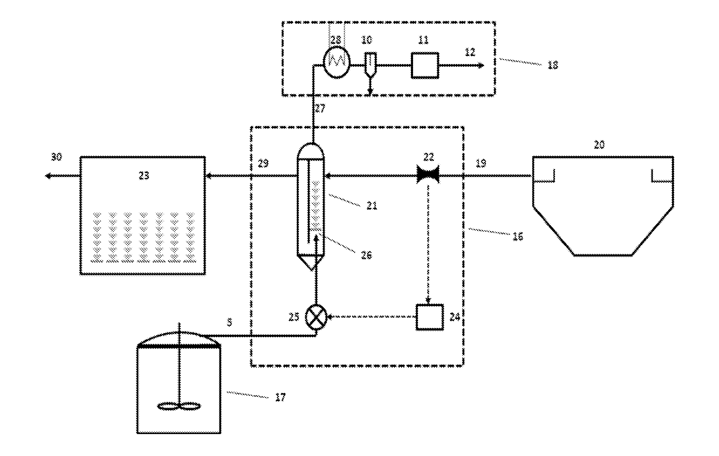
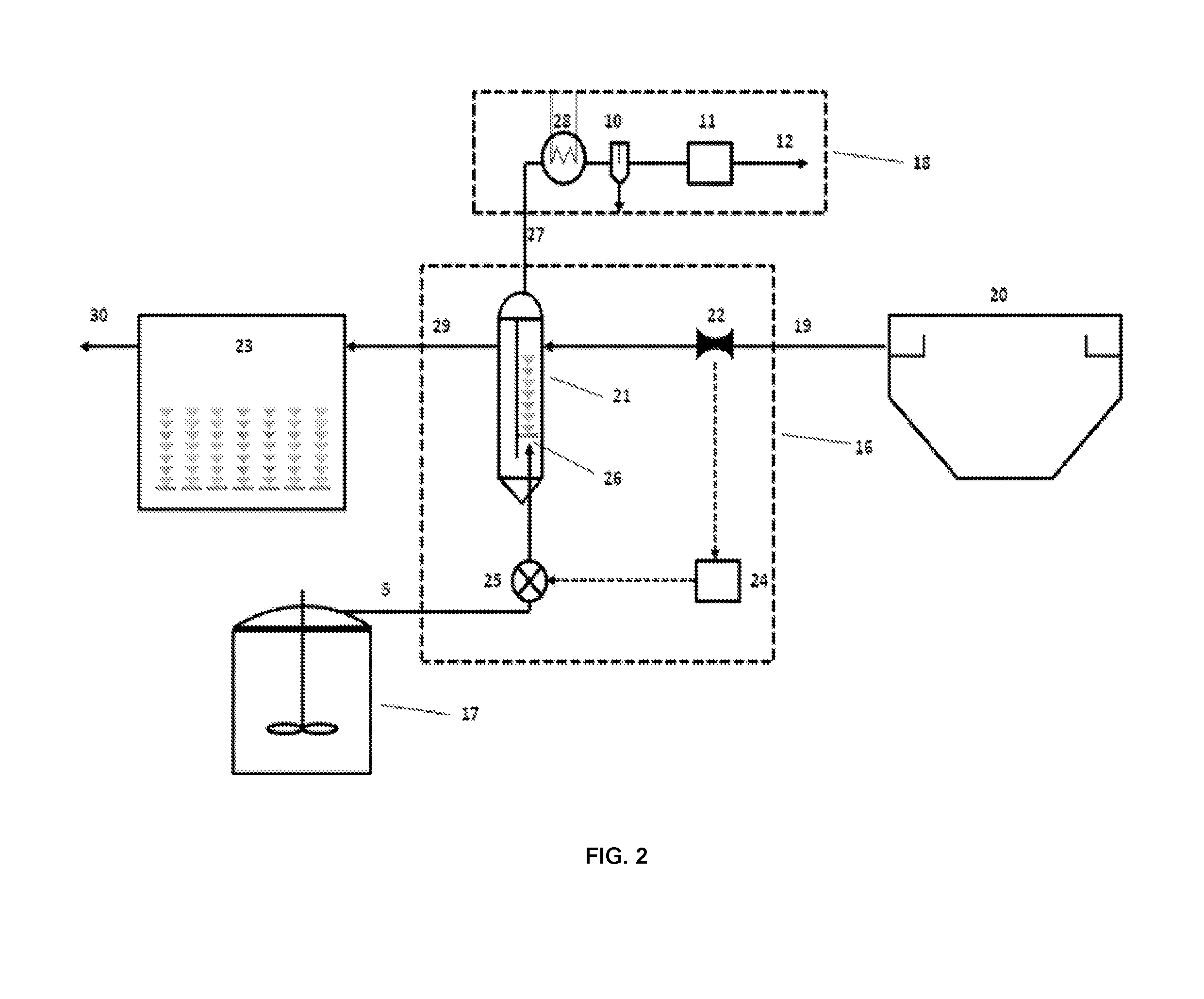
Design of a Full-Scale Biogas Upgrading Plant According to the Present Invention

[0248]Considering a wastewater treatment plant for domestic wastewaters with a daily influent flow of 60,000 m3 and a conventional technology based on activated sludge process where the sludge generated in the primary treatment (primary sludge) and a part the biosolids produced during the secondary treatment (secondary sludge) are fed to anaerobic digesters, together with other biodegradable substrates. Assuming average values of organic load and anaerobic digestion yield to methane, this facility can produce 7,000 to 11,000 m3 of raw biogas per day resulting in LI / G ratios 5.4-8.5, which are between the ranges considered in the invention herein described. It must be stressed that the daily biogas production can be considerable lower in too many cases as: digestor overloading, bad digester performance or low organic loading rates. However, these ratios will allow to produce up-graded biogas with a qualit...


PUM

PropertyMeasurementUnit
Temperatureaaaaaaaaaa
Lengthaaaaaaaaaa
Lengthaaaaaaaaaa

Abstract

A sustainable method and a system for cleaning impurities, mainly hydrogen sulphide, and upgrading of biogas having hydrogen sulphide concentration up to 2% (20,000 ppmv), preferably produced in wastewater treatment plants (WWTPs) to biomethane. The system includes a counter-current, non-pressurized physical absorption bubble column having a high influent liquid-to-gas flow ratio LI/G higher than 1 and preferably equal or higher than 3 and equal or lower than 10, for achieving a simultaneous removal of hydrogen sulphide and carbon dioxide. The system may be inserted for instance on an existing wastewater treatment plant, in such a way that the wash water is the primary treated wastewater of the plant, and preferably the biogas to be upgraded is produced in the anaerobic digesters of the plant itself, and also includes means for regenerating the used wash water by the biological reactor of the plant itself used for the secondary treatment.

Description

FIELD OF THE INVENTION[0001]This invention relates to cleaning impuritites, mainly hydrogen sulphide, and upgrading the biogas, mainly removing carbon dioxide, coming from an industrial source, for example and preferably the biogas produced in wastewater treatment plants during anaerobic digestion of sewage sludge and biosolids, to be used as fuel.BACKGROUND OF THE INVENTION[0002]Anaerobic digesters help to stabilize sewage sludge and biosolids in wastewater treatment plants before it is either used in agricultural land or dried, incinerated or landfilled.[0003]The product of anaerobic digestion, which is commonly called biogas, is a mixture primarily composed of methane and carbon dioxide, and usually undesired substances such as water, hydrogen sulphide, ammonia, oxygen, siloxanes and particulates.[0004]Hydrogen Sulphide pre-cleaning of biogas is necessary to be used as fuel for combined heat and power (CHP) units or boilers and further cleaning and upgrading is required to be use...

Claims


Application Information

Patent Timeline
IPC IPC(8): B01D53/18C02F11/04B01D53/04B01D53/14
CPCB01D53/18B01D53/1468B01D53/1425C02F11/04B01D53/04B01D2257/304B01D2253/106B01D2253/116B01D2253/102B01D2256/245B01D2252/103B01D53/1462B01D53/78B01D2257/504B01D2258/05C10L3/101Y02C20/40Y02E50/30
Inventor DE GODOS CRESPO, IGNACIOCANO HERRANZ, RA LSANTIAGO COSTA, JOSE RAMONLARA CORONA, ENRIQUELLAMAS MOYA, BERNARDO
Owner FCC AQUALIA
Why Eureka
Try Eureka