

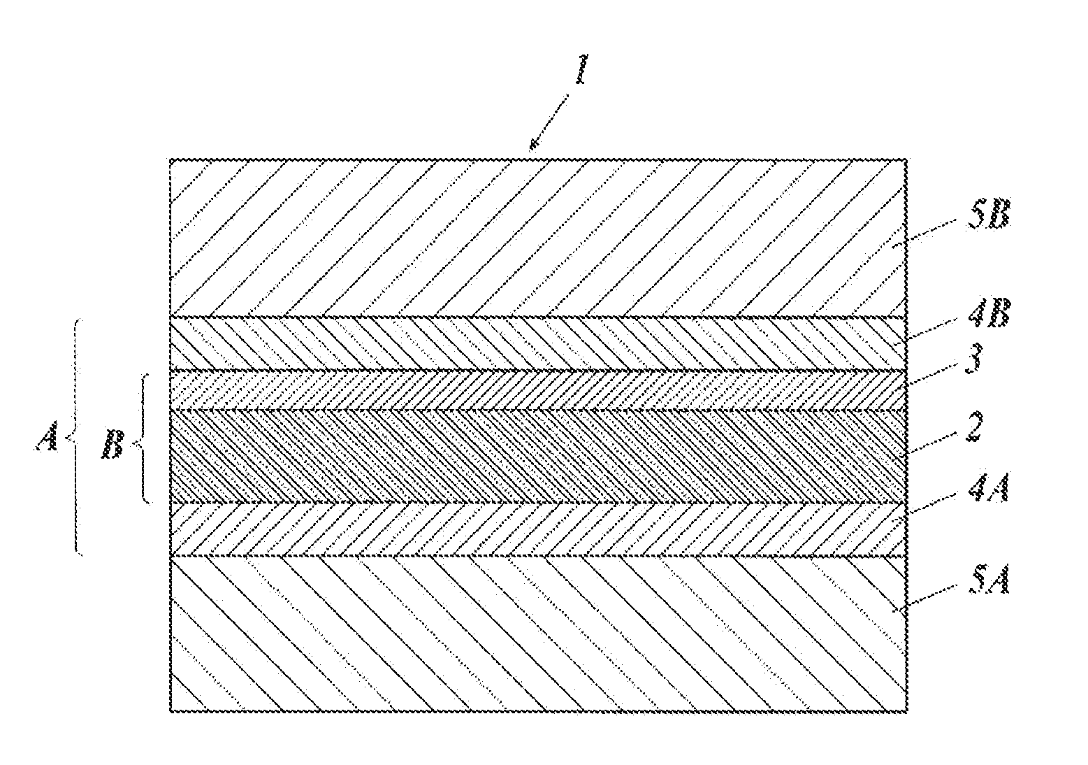
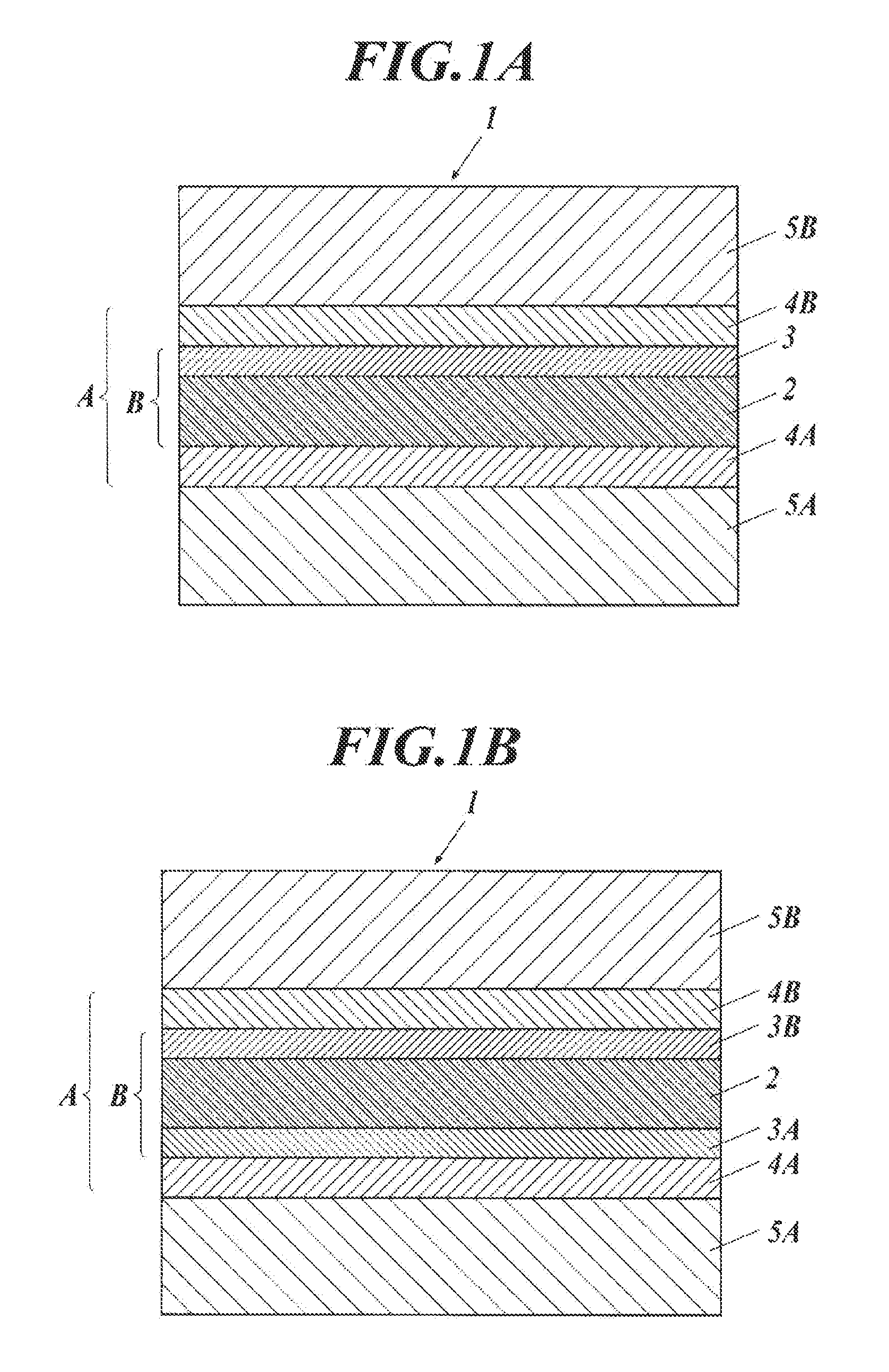
Heat ray shielding laminated glass and manufacturing method for heat ray shielding laminated glass
a technology of heat ray shielding and laminated glass, which is applied in the direction of coatings, layered products, chemistry apparatus and processes, etc., can solve the problems of high glass scattering rate, excessive adhesion of adhesive layer, and low shielding film unit, so as to reduce glass scattering rate and excellent flatness and adhesion property
- Summary
- Abstract
- Description
- Claims
- Application Information
AI Technical Summary
Benefits of technology
Problems solved by technology
Method used
Image

Examples
example 1
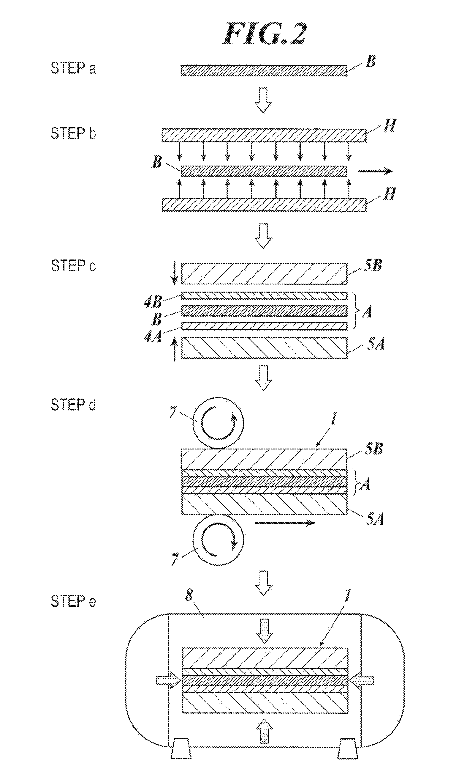
Production of Laminated Glass
[0352][Production of Laminated Glass 1]
[0353][Preparation of Coating Liquid for Forming Heat Ray Shielding Layer]
[0354](Preparation of Coating Liquid L1 for Low Refractive Index Layer)
[0355]1>
[0356]By adding pure water to have 1000 parts after mixing and dispersing each additive described below, the colloidal silica dispersion liquid L1 was prepared.
[0357]10% by mass aqueous solution of metal oxide particles (colloidal silica, manufactured by Nissan Chemical Industries, Limited, SNOWTEX (registered trademark) OXS) (680 parts)
[0358]4.0% by mass aqueous solution of polyvinyl alcohol (manufactured by KURARAY CO., LTD, PVA-103: degree of polymerization degree; 300, degree of saponification; 98.5% by mol) (30 parts)
[0359]3.0% by mass aqueous solution of boric acid (150 parts)
[0360]Subsequently, the colloidal silica dispersion liquid L1 thus obtained was heated to 45° C., and 760 parts of an aqueous solution containing 4.0% by mass of a polyvinyl alcohol (manu...
example 2
Production of Laminated Glass
[0408][Production of Laminated Glass 11]
[0409][Preparation of Heat Ray Shielding Film 11]
[0410]The heat ray shielding layer 11 consisting of total 27 layers of a refractive index layer was formed, in the same manner as production of the heat ray shielding film 1 described in Example 1, on a PET film (as defined above, Tg: 75° C.) having thickness of 50 μm as a transparent resin film. Subsequently, on a PET film (polyethylene terephthalate film) which is opposite to the surface having the heat ray shielding layer 11 formed thereon, a hard coat layer having an infrared ray absorbing property was formed in the same manner as Example 1 to produce the heat ray shielding film 11.
[0411][Preparation of Heat Ray Shielding Film Unit 11]
[0412]On both surface of the heat ray shielding film 11 which has been prepared above, polyvinyl butyral was coated using a wire bar to have thickness of 380 μm. By drying with hot air at 60° C. for 3 minutes, the adhesive layer 4A ...
example 3
Production of Laminated Glass
[0439][Preparation of Heat Ray Shielding Film 21 to 28]
[0440]The heat ray shielding film 21 to 28 were prepared in the same manner as production of the heat ray shielding film 1 of Example 1 except that the transparent resin film was changed to a PET film (as defined above, Tg: 75° C.) to a PEN film (polyethylene naphthalate film, Teonex Q81, manufactured by Teijin DuPont, Tg: 113° C.) having thickness of 50 μm, and modifications were made to have the conditions for preliminary heating described in Table 3.
[0441][Production of Laminated Glass 21 to 28]
[0442]The laminated glass 21 to 28 were produced in the same manner as the laminated glass 1 described in Example 1, except that the heat ray shielding film 21 to 28 which have been prepared above were used instead of the heat ray shielding film 1.
[0443]>
[0444]The average moisture content 1 in the above-prepared heat ray shielding film alone after a preliminary heating treatment and the average moisture con...
PUM
| Property | Measurement | Unit |
|---|---|---|
| Percent by mass | aaaaa | aaaaa |
| Percent by mass | aaaaa | aaaaa |
| Temperature | aaaaa | aaaaa |
Abstract
Description
Claims
Application Information