

Articles Coated With Fluoro-Annealed Films
- Summary
- Abstract
- Description
- Claims
- Application Information
AI Technical Summary
Benefits of technology
Problems solved by technology
Method used
Image

Examples
example 1
[0059]Material Recognition with XRD of Fully-Fluorinated Film
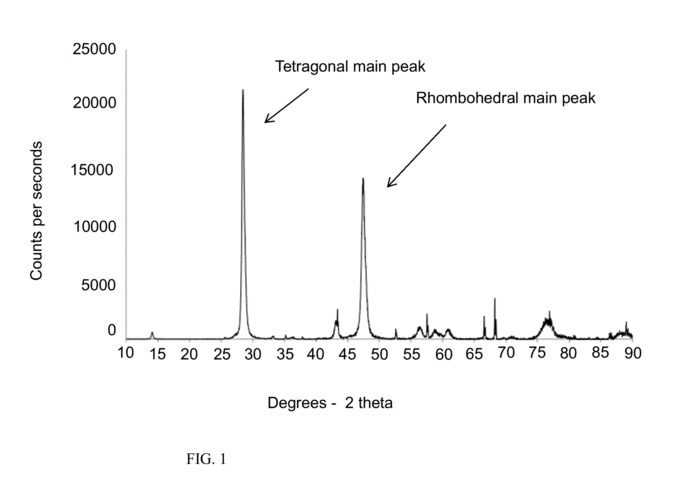
[0060]FIG. 1 is an x-ray diffraction (XRD) graph of a fluoro-annealed film in accordance with a version of the present invention, specifically a completely-fluorinated film. X-ray diffraction measurements were obtained with Scintag PAD V hardware and DMSNT software using JCPDS standards. Peak positions in the XRD graph correspond to where an x-ray beam has been diffracted by a crystal lattice. A unique set of degree-spacings in an XRD graph can be used to identify and characterize crystalline materials.
[0061]Yttria was coated onto an alumina substrate followed by fluoro-annealing at 550° C. for 4 hours in a fluorine containing atmosphere. After the fluorination process, the yttria was confirmed to have been converted to pure yttrium oxyfluoride. The XRD pattern of fluoro-annealed yttria matches the pattern of yttrium oxyfluoride. The XRD patter has first and second strong peaks at 28.3961 (+ / −0.5) and 47.2761 (+ / −0.5) degr...
example 2
[0062]Material Recognition with XRD of Partially-Fluorinated Film
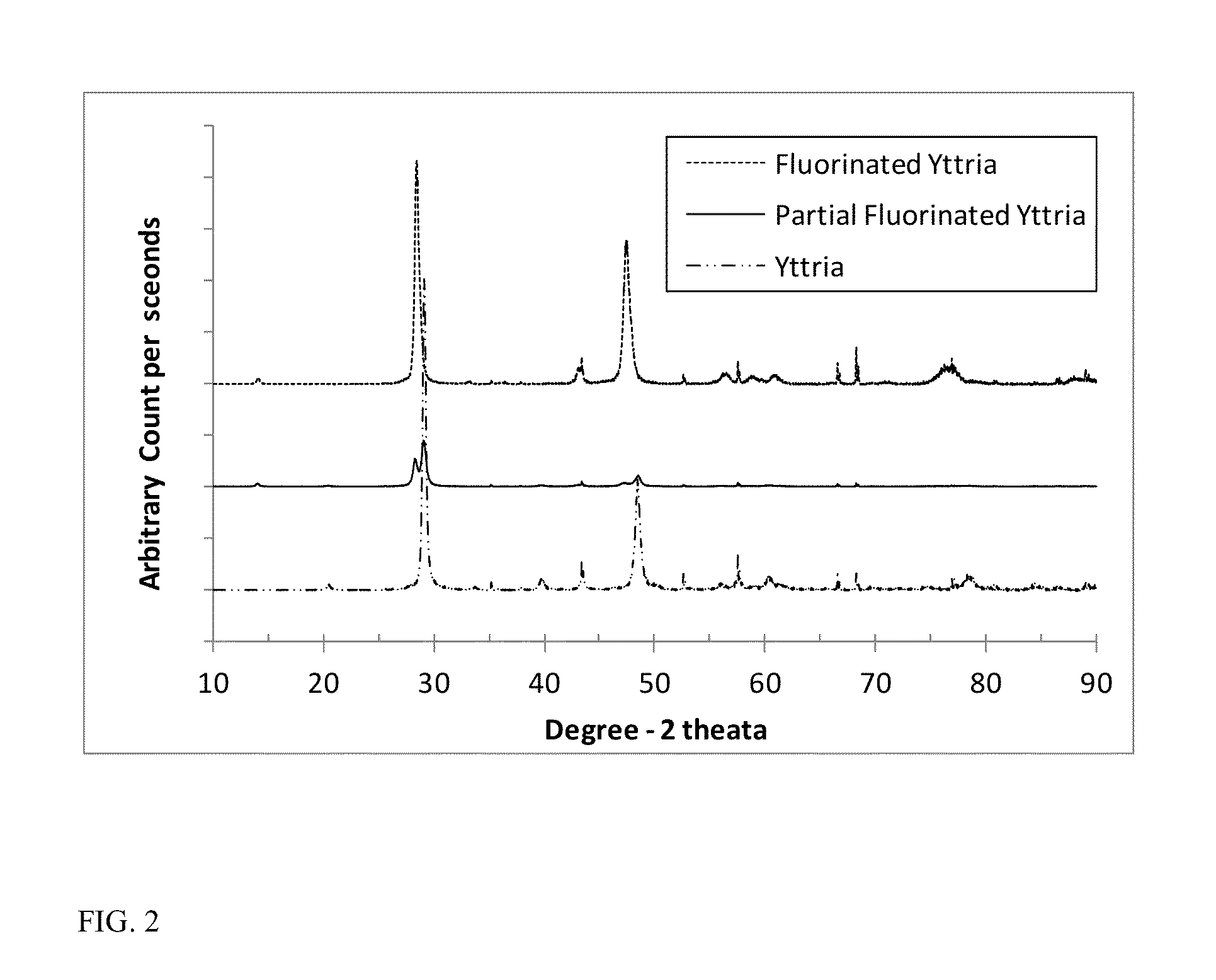
[0063]FIG. 2 is an x-ray diffraction (XRD) graph of a fluoro-annealed film in accordance with another version of the present invention, specifically a partially-fluorinated yttria film. The fluoro-annealing process was controlled to partially-fluorinate yttria by controlling the fluorine source amount, annealing temperature, and annealing time. The film was annealed at 400° C. for about 2 hours in a fluorine-containing atmosphere. In FIG. 2, the as-deposited yttria has first and second strong peaks at 28.7245 (+ / −0.5) and 47.7501 (+ / −0.5) degrees of two theta, respectively, in the XRD pattern, and its crystal system is cubic. The XRD pattern of partially-fluorinated yttria film is the combination of yttria and yttrium oxyfluoride XRD patterns, indicating that yttria and yttrium oxyfluoride co-exist in the film.
example 3
[0064]Material Recognition with XPS
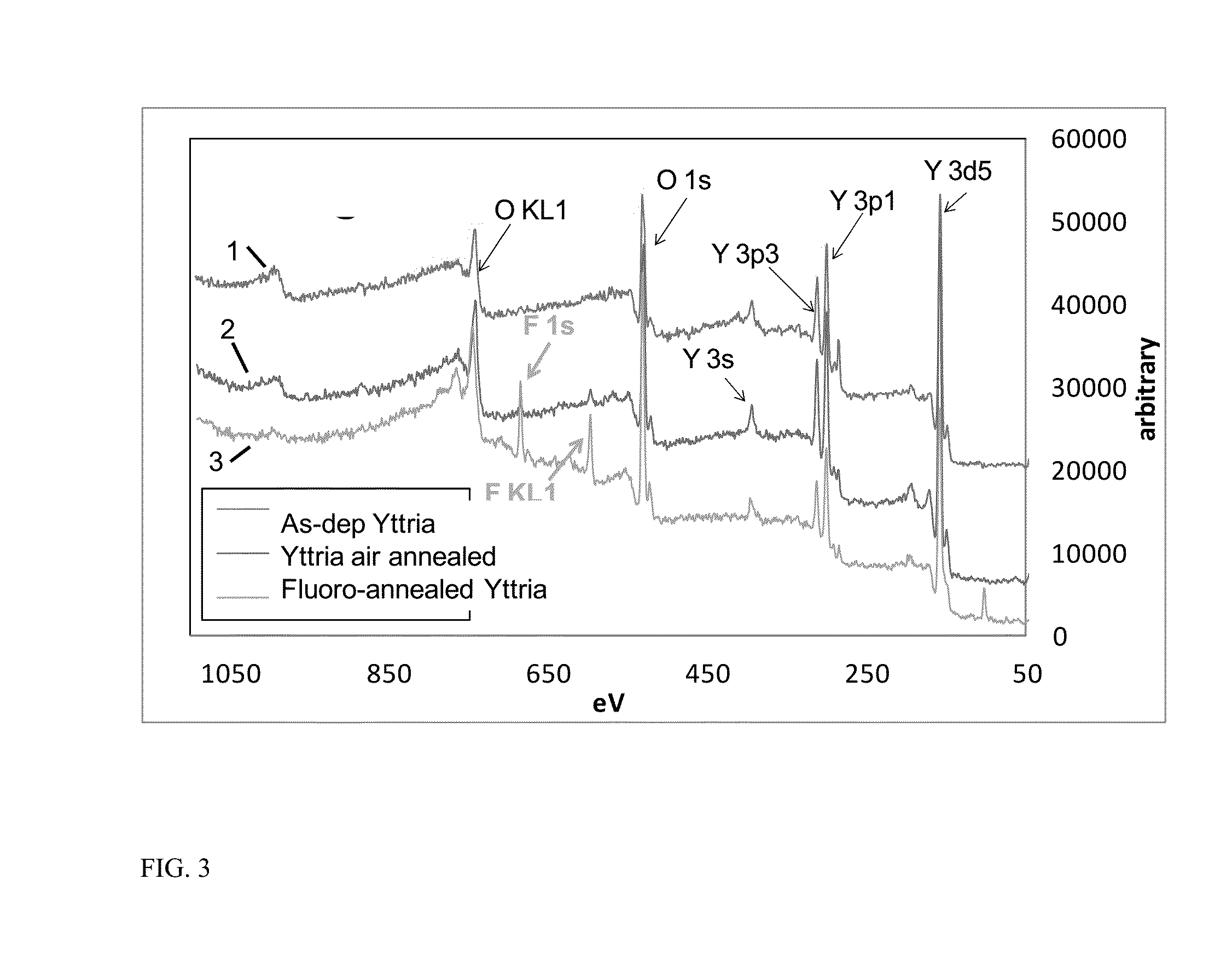
[0065]FIG. 3 is an x-ray photoelectron spectroscopy (XPS) graph illustrating the spectra of as-deposited yttria (line 1), air-annealed yttria (line 2), and fluoro-annealed yttria (line 3). XPS spectra were obtained with Vacuum Generators Escalab MK II and Avantage software.
[0066]Yttria was deposited onto an alumina substrate, and its XPS spectrum was measured prior to annealing. The XPS spectrum of the as-deposited yttria is represented by line 1. The yttria was then air-annealed at 550° C. for approximately 2 hours and its XPS spectrum measured. The XPS spectrum of the air-annealed yttria is represented by line 2. A second sample of yttria deposited onto a substrate was fluoro-annealed at 550° C. for approximately 2 hours and its measured XPS spectrum is represented by line 3.
[0067]The XPS spectra of as-deposited yttria film and the air-annealed yttria film show strong oxygen (O) and yttrium (Y) peaks. The XPS spectrum of the fluoro-annealed yttri...
PUM
| Property | Measurement | Unit |
|---|---|---|
| Temperature | aaaaa | aaaaa |
| Temperature | aaaaa | aaaaa |
| Fraction | aaaaa | aaaaa |
Abstract
Description
Claims
Application Information